
Temporary support device for wind power generation

A temporary support and support plate technology, which is applied in the direction of wind power generation, wind engine, installation/support of wind engine configuration, etc., can solve the problem of inability to raise the universal wheel, reduce the scope of application of the support device, and not be able to flexibly adjust the support Problems such as angle and height can achieve the effect of increasing the scope of application, increasing practicality and increasing flexibility

Active Publication Date: 2019-01-15
重庆市宝盈机械制造有限公司
View PDF4 Cites 3 Cited by
  • Summary
  • Abstract
  • Description
  • Claims
  • Application Information

AI Technical Summary

Problems solved by technology

[0002] In the process of wind power construction, it is necessary to support and fix the tower column. The structure of the existing support device is rigid, and it is impossible to realize the lifting of the universal wheel when moving. The flexibility of the protective device structure makes it impossible to flexibly transform between moving and fixing, and the angle of the fixing jacket cannot be adjusted. When fixing, the angle and height of the support cannot be flexibly adjusted, and the support device cannot be added. practicability, it is not possible to fix towers with different diameters, which reduces the scope of application of the support device

Method used


Image

  • Temporary support device for wind power generation
  • Temporary support device for wind power generation
  • Temporary support device for wind power generation

Examples


Embodiment Construction

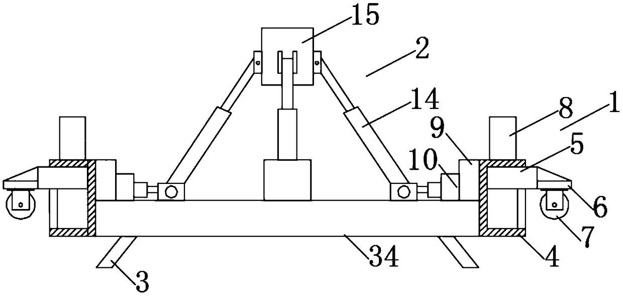
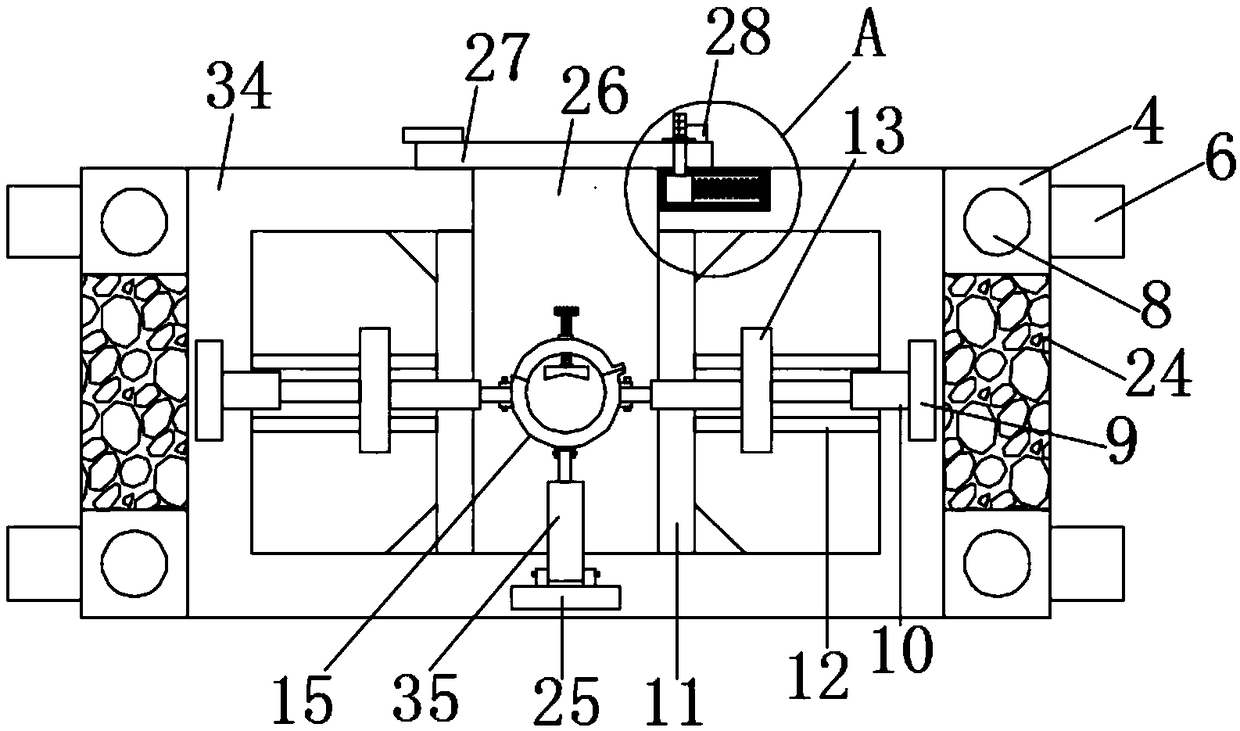
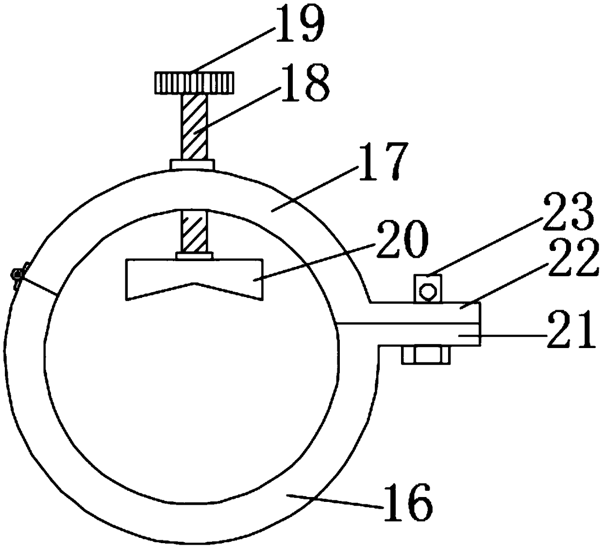
[0021] Such as Figure 1-5 As shown, this specific embodiment adopts the following technical solutions: a temporary support device for wind power generation, including a moving mechanism 1 and a fixing mechanism 2, the fixing mechanism 2 is arranged above the moving mechanism 1, and the moving mechanism 1 is composed of The anti-skid strut 3, the lifting chute 4, the lifting slider 5, the supporting plate 6, the universal wheel 7, the third hydraulic cylinder 8 and the supporting bottom frame 34 are formed, and the bottom of the supporting bottom frame 34 is equidistantly fixedly connected with four Two anti-skid poles 3, and the corresponding two sides of the support bottom frame 34 are fixedly connected with two lifting chute 4, the top of the lifting chute 4 is fixedly connected with the third hydraulic cylinder 8, and the lifting chute 4 is fixedly connected with the third hydraulic cylinder 8. The interior of 4 is fixedly and slidably connected with a lifting slider 5, th...


PUM


Abstract

The invention discloses a temporary support device for wind power generation, which comprises a moving mechanism and a fixed mechanism, wherein the fixed mechanism is arranged on the moving mechanism,and the moving mechanism is composed of antiskid supporting rods, lifting sliding slots, lifting sliding blocks, supporting plates, universal wheels, third hydraulic cylinders and a supporting bottomframe. The temporary support device is provided with the moving mechanism, the lifting of the universal wheels is realized through the third hydraulic cylinders when the temporary support device moves, and the temporary support device directly lifts the universal wheels and is supported by the supporting bottom frame when being supported and fixed, so that the structural flexibility of the support device is increased, and the temporary support device is enabled to be flexibly transformed between movement and fixation. The temporary support device is provided with first hydraulic cylinders andsecond hydraulic cylinders, thereby being capable of adjusting the angle of a fixing clamp sleeve. The height and angle of the support can be flexibly adjusted when the temporary support device is fixed, so that practicability of the support device is increased. The temporary support device is provided with a fixing lead screw and a fastening sliding block, thereby being capable of fixing tower piles with different diameters, and increasing the application range of the support device.

Description

Technical field: [0001] The invention relates to the technical field of wind power generation equipment, in particular to a temporary support device for wind power generation. Background technique: [0002] In the process of wind power construction, it is necessary to support and fix the tower column. The structure of the existing support device is rigid, and it is impossible to realize the lifting of the universal wheel when moving. The flexibility of the protective device structure makes it impossible to flexibly transform between moving and fixing, and the angle of the fixing jacket cannot be adjusted. When fixing, the angle and height of the support cannot be flexibly adjusted, and the support device cannot be added. Due to the practicability, it is not possible to fix towers with different diameters, which reduces the scope of application of the support device. Invention content: [0003] The object of the present invention is to provide a temporary support device fo...

Claims


Application Information

Patent Timeline
Patent Type & Authority Applications(China)
IPC IPC(8): F03D13/20F03D80/00F03D9/11
CPCF03D9/11F03D13/22F03D80/00Y02E10/72Y02E10/728Y02E70/30
Inventor 余彬楠
Owner 重庆市宝盈机械制造有限公司
Learn More