Position based impedance control method and system for hydraulic driving unit

An impedance control and drive unit technology, which is applied to fluid pressure actuation system components, fluid pressure actuation devices, motor vehicles, etc., can solve the problems of position control accuracy influence, dynamic influence of position control accuracy, and accuracy reduction, etc. The effect of improving anti-jamming performance, optimizing dynamic compliance, and increasing dynamic stiffness

Active Publication Date: 2019-01-15
YANSHAN UNIV
View PDF3 Cites 9 Cited by
  • Summary
  • Abstract
  • Description
  • Claims
  • Application Information

AI Technical Summary

Problems solved by technology

However, in practice, due to the disturbance force of the position control system of the hydraulic drive unit and the uncertainty of the environment, the disturbance force and load characteristics will affect the position control accuracy, especially when the disturbance force and load characteristics change dynamically. Together with the inherent nonlinearity, time-varying parameters and strong coupling of the hydraulic system, it will have a dynamic impact on the position control accuracy, which is manifested in the fact that the dynamic compliance of the inner ring of the position control of the hydraulic drive unit is not zero.
At this time, the position control accuracy of the inner ring of the hydraulic drive unit decreases, which affects the overall compliance control accuracy of the legged robot
[0007] On the other hand, when the traditional position-based impedance control system is subjected to different types of disturbance forces, there are large position deviations and phase angle deviations between the actual position and the expected position of the impedance control
For the high-precision control requirements of legged robots, the lack of control performance of the traditional position-based impedance control obviously cannot meet the control accuracy requirements.

Method used


Image

  • Position based impedance control method and system for hydraulic driving unit
  • Position based impedance control method and system for hydraulic driving unit
  • Position based impedance control method and system for hydraulic driving unit

Examples


Embodiment Construction

[0067] The following will clearly and completely describe the technical solutions in the embodiments of the present invention with reference to the accompanying drawings in the embodiments of the present invention. Obviously, the described embodiments are only some, not all, embodiments of the present invention. Based on the embodiments of the present invention, all other embodiments obtained by persons of ordinary skill in the art without making creative efforts belong to the protection scope of the present invention.

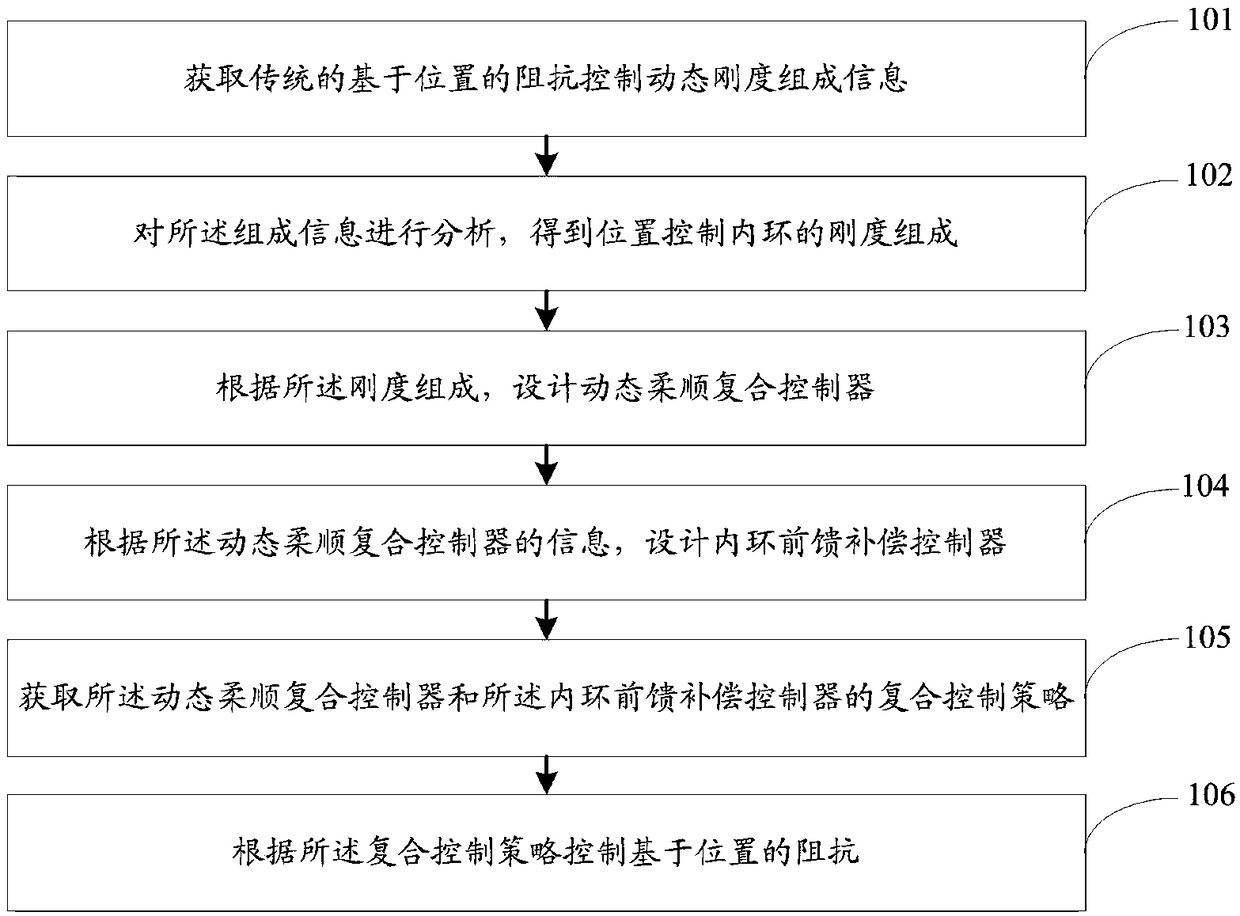
[0068] The object of the present invention is to provide a position-based impedance control method and system for a hydraulic drive unit, which can significantly improve the position-based impedance control accuracy.

[0069] In order to make the above objects, features and advantages of the present invention more comprehensible, the present invention will be further described in detail below in conjunction with the accompanying drawings and specific embodiment...


PUM


Abstract

The invention discloses a position based impedance control method and system for a hydraulic driving unit. The method comprises that dynamic rigidity composition information of traditional position based impedance control is obtained; the composition information is analyzed to obtain inner-ring rigidity composition of position control; a dynamic submissive composite controller is designed according to the rigidity composition; according to information of the dynamic submissive composite controller, an inner-ring feedforward compensation controller is designed; a composite control strategy of the dynamic submissive composite controller and the inner-ring feedforward compensation controller are obtained; and the position based impedance is controlled according to the composite control strategy. The method and system of the invention can be used to improve the position based impedance control precision substantially.

Description

technical field [0001] The invention relates to the field of fluid transmission and control, in particular to a position-based impedance control method and system for a hydraulic drive unit. Background technique [0002] Compared with wheeled, tracked and spherical robots, footed robots have good adaptability to unknown and unstructured environments, can cross obstacles, and have unique advantages when performing tasks in unknown wild environments. research hotspot. Nowadays, the joint drives of hydraulic-driven legged robots generally adopt a highly integrated valve-controlled cylinder structure, which is also called a hydraulic drive unit. The hydraulic drive unit is used as the joint driver of the legged robot, which not only brings the high-performance advantages of the hydraulic system, but also brings common problems of the hydraulic system such as strong nonlinearity and time-varying parameters, which makes the control of the robot more difficult. increase. [0003...

Claims


Application Information

Patent Timeline
Patent Type & Authority Applications(China)
IPC IPC(8): F15B21/08B62D57/032
CPCB62D57/032F15B21/087
Inventor 巴凯先俞滨马国梁金正国孔祥东
Owner YANSHAN UNIV
Why Eureka
Try Eureka