

Micro-slip control system for wet double clutch automatic transmission
A wet dual clutch, automatic transmission technology, applied in transmission control, transmission parts, gear lubrication/cooling, etc., can solve the problem of excessive target slip and actual slip, clutch stuck, clutch ablation and other problems, to achieve the effect of easy implementation, convenient data collection, and easy application
- Summary
- Abstract
- Description
- Claims
- Application Information
AI Technical Summary
Problems solved by technology
Method used
Image

Examples
Embodiment Construction
[0047] The technical solution of the present invention is described in detail below through the examples, and the following examples are only exemplary and can only be used to explain and illustrate the technical solution of the present invention, rather than being interpreted as a limitation to the technical solution of the present invention.
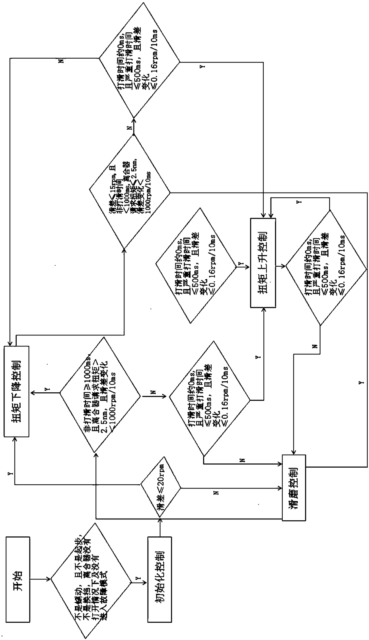
[0048] A micro-slip control method for a wet dual-clutch automatic transmission, such as figure 1 As shown, including initialization control, torque down control, torque up control and micro-slip grinding control.
[0049] Before the gearbox is controlled, it is first judged whether the gearbox meets the micro-slip control conditions. The micro-slip control conditions include that the gearbox is not creeping, it is not starting, it is not shifting, the clutch is not Open and not in failure mode.
[0050] After judging, if it matches, then proceed to the initialization control stage.
[0051] Under the initial control condition, it is...
PUM
 Abstract
Description
Claims
Application Information