Dehumidification and humidification rotor

A rotor and air hole technology, applied in the field of dehumidification and humidification rotors, can solve the problems of time-consuming, low manufacturing efficiency, and reduced range, and achieve the effects of easy manufacturing, good efficiency, and increased range

Inactive Publication Date: 2019-01-15
TECHNO FRONTIER
View PDF10 Cites 3 Cited by
  • Summary
  • Abstract
  • Description
  • Claims
  • Application Information

AI Technical Summary

Problems solved by technology

[0004] The dehumidification and humidification device described in Patent Document 1 has the disadvantage that it takes man-hours to manufacture
That is, it is necessary to wind the strip-shaped corrugated paper in a cylindrical shape to produce a roll body with a large thickness dimension, and also to cut the roll body into a small thickness dimension. The production efficiency is low, and it takes man-hours.
In addition, there is a problem that the passing air is a laminar flow, and the air does not fully contact the moisture-absorbing powder (diatomaceous earth)
That is, there is a disadvantage that the efficiency of dehumidification and humidification is poor
Moreover, there is also the following disadvantage: since the strip-shaped corrugated paper is wound and installed on the rotating shaft during manufacture, a central through hole is formed in the dehumidification and humidification rotor, and the range that can dehumidify and humidify the air is reduced by an amount equivalent to this. Amount of central through hole

Method used


Image

  • Dehumidification and humidification rotor
  • Dehumidification and humidification rotor
  • Dehumidification and humidification rotor

Examples


Embodiment Construction

[0014] Hereinafter, the present invention will be described in detail based on the illustrated embodiments.

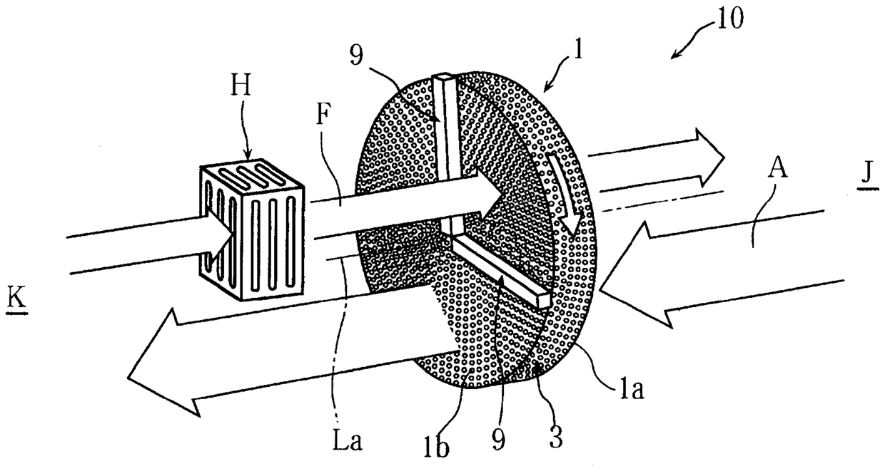
[0015] figure 1 Showing the first embodiment of the present invention, this dehumidification and humidification rotor is used in a desiccant air conditioner and is also called a desiccant rotor.

[0016] Such as figure 1 As shown, the desiccant-type air conditioner 10 is configured to rotate the dehumidification and humidification rotor 1 around the rotor axis La, suck in the process air A containing moisture (moisture) from the side J of the rotor axis, and pass the process air A A part of the dehumidifying and humidifying rotor 1 absorbs moisture, and the hot air F heated by a heat source H such as a heater passes through the remaining part of the dehumidifying and humidifying rotor 1 from the other side K of the rotor axis to discharge the adsorbed moisture to one side of the axis J Conveying hot air F containing moisture. The rotational speed of the dehumidifica...


PUM

PropertyMeasurementUnit
diameteraaaaaaaaaa

Abstract

The invention provides a dehumidification and humidification rotor capable of being manufactured easily. The dehumidification and humidification rotor is configured to be disciform in overall shape and to be made of foaming ceramic (3) having a plurality of connected pores (2). The foaming ceramic (3) contains moisture adsorbing powder (4). The moisture adsorbing powder (4) is exposed on the innersurfaces (5) of the pores (2), and air passing through the pores (2) is in contact with the exposed moisture adsorbing powder (4).

Description

technical field [0001] The invention relates to a dehumidifying and humidifying rotor. Background technique [0002] As a conventional dehumidification and humidification rotor, for example, there is a device in which strip-shaped corrugated paper impregnated with diatomaceous earth is rolled and installed in a cylindrical shape (for example, refer to Patent Document 1). [0003] Patent Document 1: Japanese Patent No. 5643802. [0004] The dehumidification and humidification device described in Patent Document 1 has a drawback that it takes man-hours to manufacture. That is, a process of manufacturing a roll body with a large thickness by winding a strip-shaped corrugated paper in a cylindrical shape is required, and a process of cutting the roll body into a small thickness dimension is required, and the production efficiency is low and labor-intensive. In addition, there was a problem that the passing air was a laminar flow, and the air did not sufficiently contact the mo...

Claims


Application Information

Patent Timeline
Patent Type & Authority Applications(China)
IPC IPC(8): F24F3/14B01D53/26
CPCB01D53/261F24F3/1429F24F2203/1032
Inventor 河原利和
Owner TECHNO FRONTIER
Why Eureka
Try Eureka