Control circuit for magnetic resonance radio frequency transmitting link and magnetic resonance radio frequency transmitting system

A technology of radio frequency transmission and control circuit, which is applied in the directions of magnetic resonance measurement, magnetic variable measurement, and measurement devices, etc., which can solve problems such as complex system structure and hardware cost, and achieve simplified system structure, reduced hardware cost, and easy integration Effect

Active Publication Date: 2019-01-15
SIEMENS SHENZHEN MAGNETIC RESONANCE
View PDF7 Cites 4 Cited by
  • Summary
  • Abstract
  • Description
  • Claims
  • Application Information

AI Technical Summary

Problems solved by technology

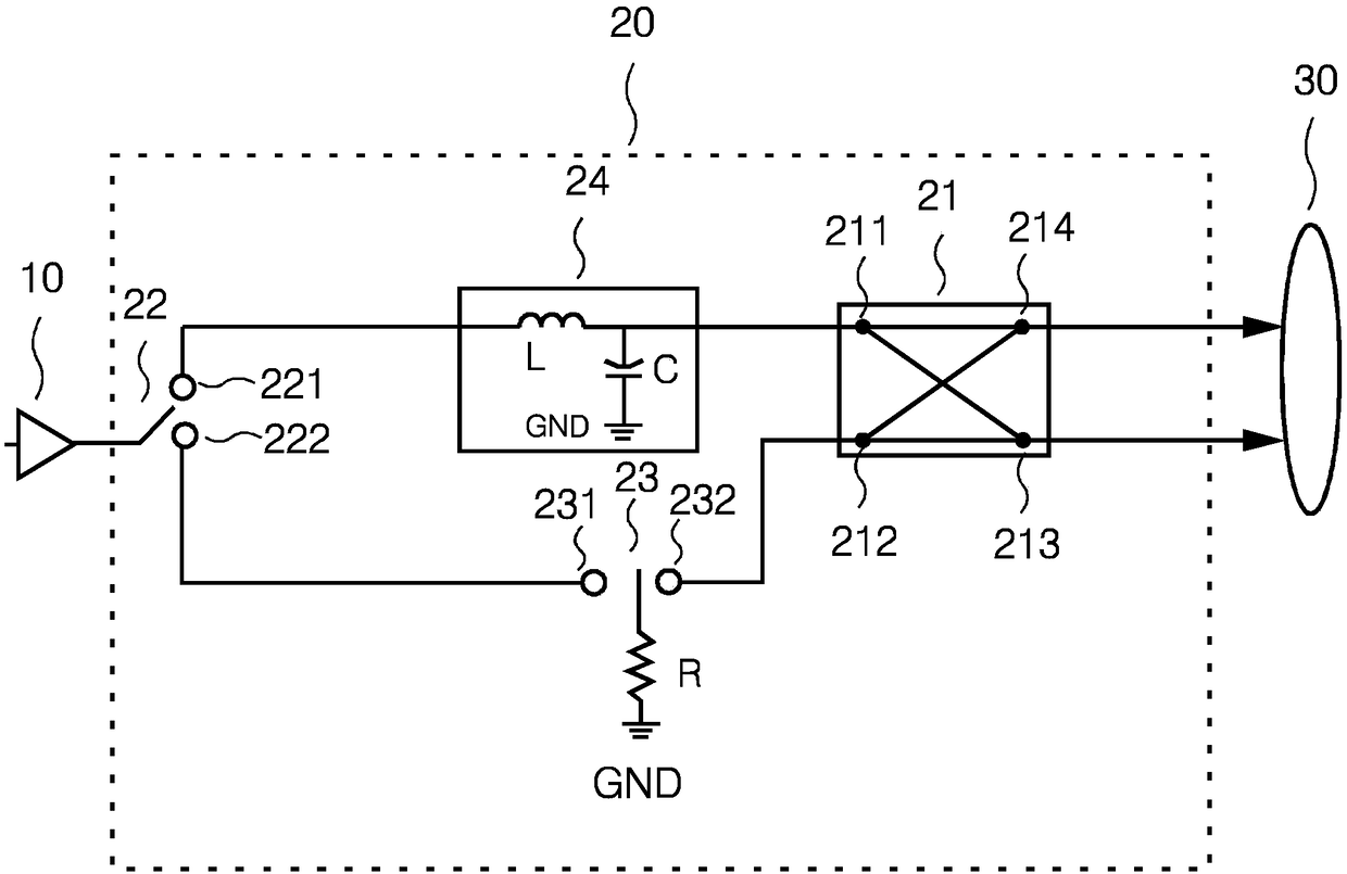
However, arranging two SPDT switches leads to hardware cost issues
Moreover, the existence of two independent control signal sources also leads to a complex system structure

Method used


Image

  • Control circuit for magnetic resonance radio frequency transmitting link and magnetic resonance radio frequency transmitting system
  • Control circuit for magnetic resonance radio frequency transmitting link and magnetic resonance radio frequency transmitting system
  • Control circuit for magnetic resonance radio frequency transmitting link and magnetic resonance radio frequency transmitting system

Examples


Embodiment Construction

[0057] In order to make the technical solutions and advantages of the present invention clearer, the present invention will be further described in detail below in conjunction with the accompanying drawings and embodiments. It should be understood that the specific embodiments described here are only used to illustrate the present invention, and are not intended to limit the protection scope of the present invention.

[0058] For the sake of brevity and intuition in description, the solution of the present invention is described below by describing several representative implementation manners. Numerous details in the embodiments are only used to help the understanding of the solutions of the present invention. But obviously, the technical solutions of the present invention may not be limited to these details when implemented. In order to avoid unnecessarily obscuring the solution of the present invention, some embodiments are not described in detail, but only a framework is gi...


PUM


Abstract

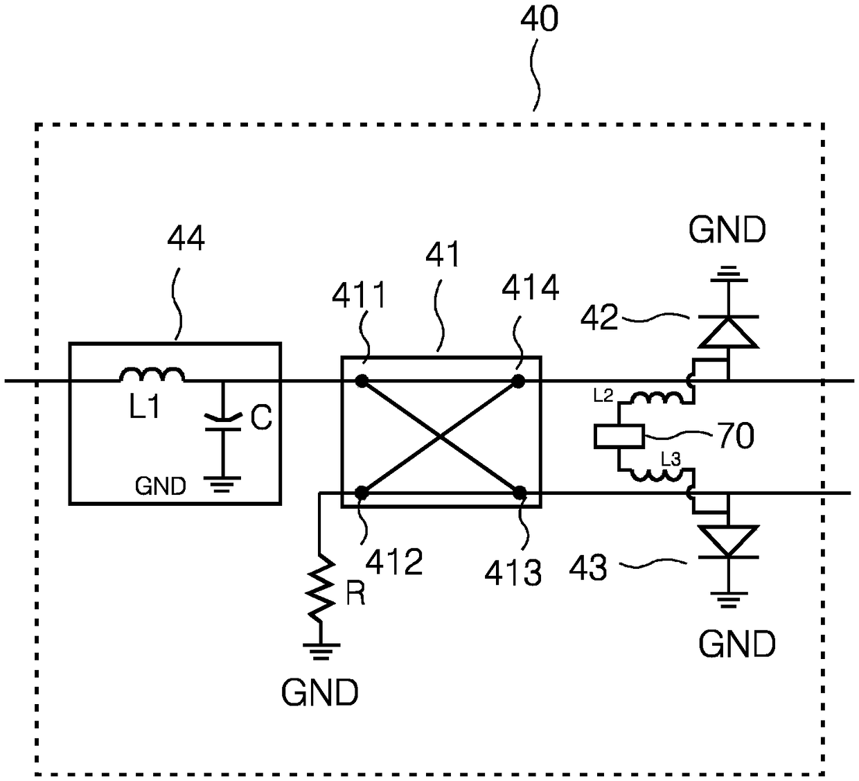
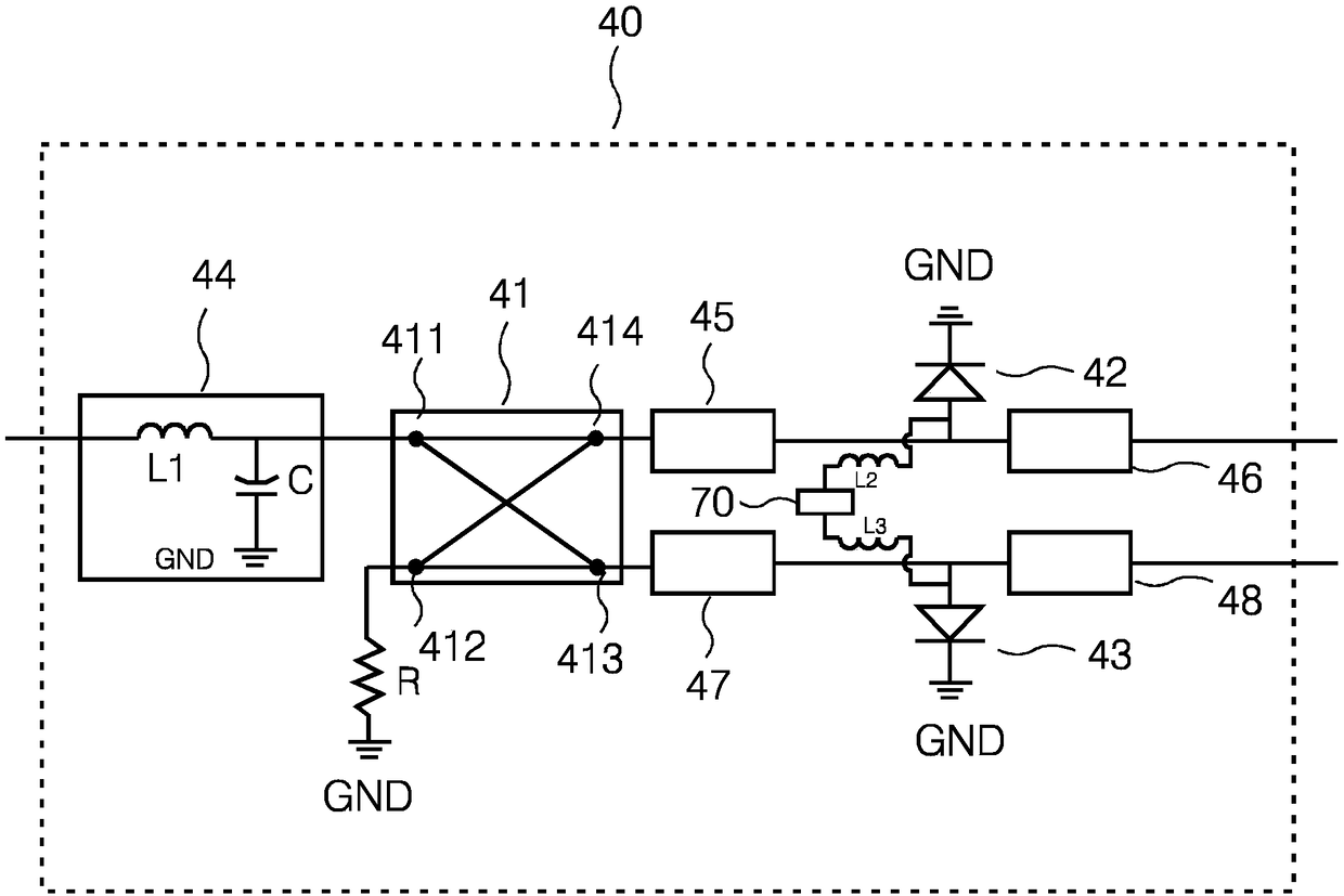
Embodiments of the invention disclose a control circuit for a magnetic resonance radio frequency transmitting link and a magnetic resonance radio frequency transmitting system. The control circuit comprises the following parts: a bridge, containing a first radio frequency signal output port and a second radio frequency signal output port, which are respectively connected to a transmitting coil; afirst PIN diode, of which the positive pole is connected to the first radio frequency signal output port, and the negative pole is grounded; a second PIN diode, of which the positive pole is connectedto the second radio frequency signal output port, and the negative pole is grounded, wherein the control end of the first PIN diode and the control end of the second PIN diode are connected to the same control signal source. The embodiments of the invention can reduce hardware cost, reduce structural complexity, and reduce the reflected power of the radio frequency power source.

Description

technical field [0001] The invention relates to the technical field of magnetic resonance imaging, in particular to a control circuit of a magnetic resonance radio frequency transmission link and a magnetic resonance radio frequency transmission system. Background technique [0002] Magnetic resonance imaging (Magnetic Resonance Imaging, MRI) is a biomagnetic nuclear spin imaging technology developed rapidly with the development of computer technology, electronic circuit technology, and superconductor technology. It uses a magnetic field and radio frequency pulses to vibrate the precessing hydrogen nuclei (ie H+) in human tissue to generate radio frequency signals, which are processed by a computer and imaged. When an object is placed in a magnetic field, it is irradiated with appropriate electromagnetic waves to make it resonate, and then the electromagnetic waves released by it are analyzed, and the position and type of the atomic nuclei that make up the object can be know...

Claims


Application Information

Patent Timeline
Patent Type & Authority Applications(China)
IPC IPC(8): G01R33/36
CPCG01R33/3607G01R33/3628G01R33/3614G01R33/3664G01R33/3678
Inventor 程鸿李志宾李文明韦斯特·马库斯
Owner SIEMENS SHENZHEN MAGNETIC RESONANCE
Why Eureka
Try Eureka