A polarizing device and an optical alignment device

A technology of mounting frame and wire grid, which is applied in optics, polarizing elements, optical elements, etc., can solve the problem that the resolution of the polarizing device cannot meet the actual needs of use, and can increase the rotation radius, improve the resolution, and improve the fine-tuning accuracy. Effect

Active Publication Date: 2021-03-09
SHANGHAI MICRO ELECTRONICS EQUIP (GRP) CO LTD
View PDF6 Cites 0 Cited by
  • Summary
  • Abstract
  • Description
  • Claims
  • Application Information

AI Technical Summary

Problems solved by technology

[0010] The purpose of the present invention is to provide a polarizing device and an optical alignment device to solve the problem that the resolution of the existing polarizing device cannot meet the needs of actual use

Method used


Image

  • A polarizing device and an optical alignment device
  • A polarizing device and an optical alignment device
  • A polarizing device and an optical alignment device

Examples


Embodiment 1

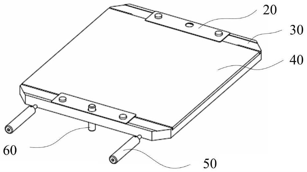
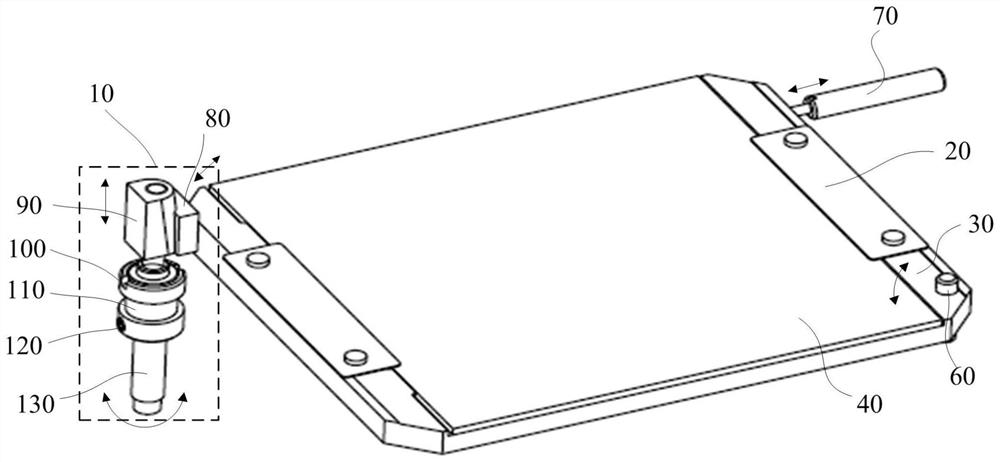
[0033] figure 2 It is a structural diagram of the polarizer provided by Embodiment 1 of the present invention, as shown in figure 2 As shown, it includes a wire grid adjusting unit 10 , a wire grid pressing piece 20 , a wire grid frame plate 30 , a polarizing wire grid 40 , a rotating shaft 60 , and a spring plunger 70 . Both sides of the polarizing wire grid 40 are connected with wire grid frame plates 30 to form a wire grid plane. The wire grid frame plates 30 are used to support the polarizing wire grid 40. The normal direction of the polarizing wire grid 40 is the rotation axis and is rotatably installed on the installation frame. The polarizing wire grid 40 is fixed on the wire grid frame plate 30 by two wire grid pressing pieces 30 through fixing screws, and the rotation axis 60 is fixed on the wire grid frame plate 30, located on the corner of the wire grid plane, and The plane is vertical, and the rotation axis 60 of the wire grid frame plate 30 and the driving for...

Embodiment 2

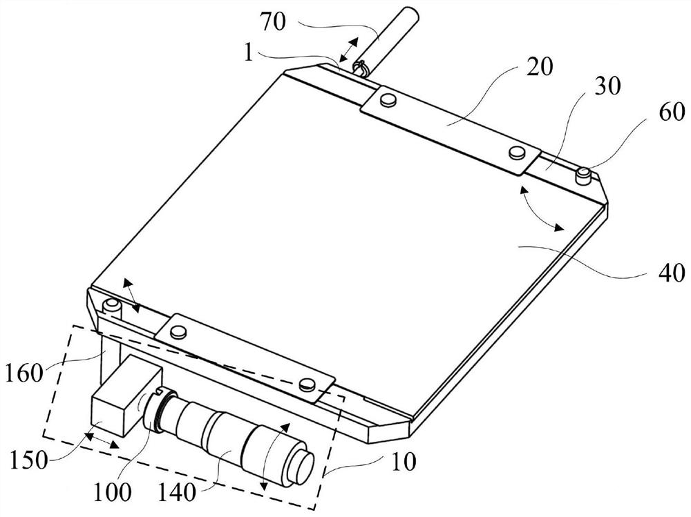
[0045] image 3 It is the structural diagram of the polarizer provided by the second embodiment of the present invention, as shown in image 3 As shown, it includes a wire grid adjusting unit 10 , a wire grid pressing piece 20 , a wire grid frame plate 30 , a polarizing wire grid 40 , a rotating shaft 60 , and a spring plunger 70 . Both sides of the polarizing wire grid 40 are connected with wire grid frame plates 30 to form a wire grid plane. The wire grid frame plates 30 are used to support the polarizing wire grid 40. The normal direction of the polarizing wire grid 40 is the rotation axis and is rotatably installed on the installation frame. The polarizing wire grid 40 is fixed on the wire grid frame plate 30 by two wire grid pressing pieces 30 through fixing screws, and the rotation axis 60 is fixed on the wire grid frame plate 30, located on the corner of the wire grid plane, and The plane is vertical, and the rotation axis 60 of the wire grid frame plate 30 and the dr...


PUM


Abstract

The present invention provides a polarizing device and an optical alignment device, including a polarizing unit and a mounting frame, and the polarizing unit includes a polarizing wire grid, a wire grid frame plate, and a wire grid adjustment unit. The wire grid frame plate is used to support the polarized wire grid, and the wire grid frame plate is rotated and installed on the installation frame with the normal direction of the polarized wire grid as the rotation axis, and the wire grid adjustment unit is The rotation of the wire grid frame plate provides the driving force, the rotation axis of the wire grid frame plate and the driving force point of the wire grid adjustment unit are located on a pair of opposite corners of the wire grid plane of the polarizing wire grid, solving The problem that the adjustment resolution of the existing polarizing device cannot meet the needs of actual use is solved.

Description

technical field [0001] The invention relates to the technical field of semiconductor manufacturing, in particular to a polarizing device and an optical alignment device. Background technique [0002] A liquid crystal display panel (LCD) generally includes two substrates (array substrate TFT, color filter substrate CF), a liquid crystal layer between the two substrates, and a polarizer outside the two substrates. In liquid crystal display technology, an electric field is generated in the liquid crystal layer by applying a voltage, thereby changing the twist angle of the liquid crystal molecules, and matching with the two polarizers on the outside of the upper and lower substrates to produce image display. [0003] However, in order to ensure the display effect of images, the liquid crystal molecules need to have an initial alignment direction, so an alignment film layer needs to be provided on the substrate, which can align the liquid crystals in a certain direction. That is...

Claims


Application Information

Patent Timeline
Patent Type & Authority Patents(China)
IPC IPC(8): G02B5/30G02F1/1335G02F1/1337
CPCG02B5/3058G02F1/133528G02F1/133788G02F1/133548
Inventor 赵灿武朱树存
Owner SHANGHAI MICRO ELECTRONICS EQUIP (GRP) CO LTD
Why Eureka
Try Eureka