Supercharge Your Innovation With Domain-Expert AI Agents!

Optical coupling device

A technology for optical coupling devices and mounting components, which is applied in the direction of electromagnetic transceivers, electrical components, and electrical solid devices, and can solve problems affecting the characteristics of optical coupling devices, etc.

Active Publication Date: 2019-01-15
KK TOSHIBA +1
View PDF7 Cites 0 Cited by
  • Summary
  • Abstract
  • Description
  • Claims
  • Application Information

AI Technical Summary

Problems solved by technology

In the case of using the photocoupler in a harsh environment with high temperature and high humidity, there is concern that the characteristics of the photocoupler may be affected due to peeling and thermal deterioration of the resin

Method used


Image

  • Optical coupling device
  • Optical coupling device
  • Optical coupling device

Examples


Embodiment Construction

[0012] The embodiments will be described below with reference to the drawings. In the following description, the same reference numerals are assigned to the same members, and the description of the members that have been described is omitted as appropriate.

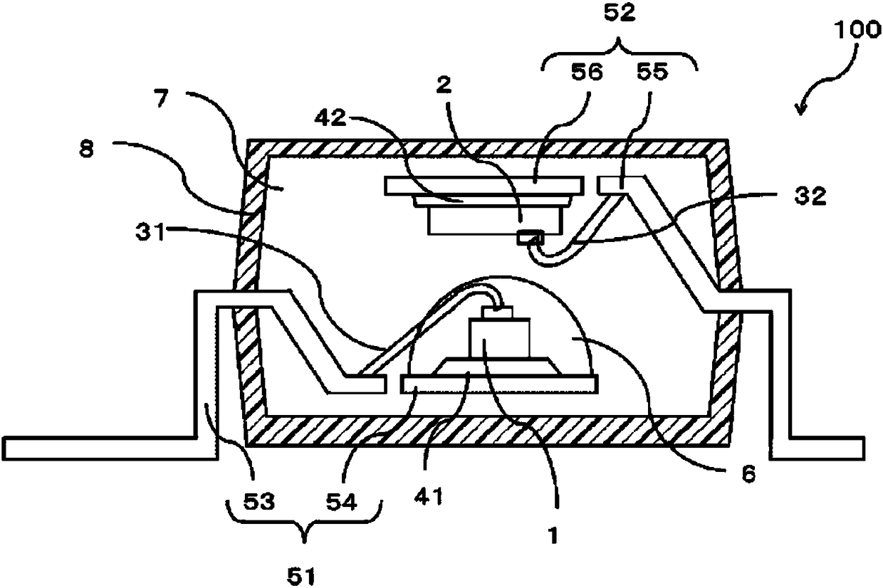
[0013] Such as figure 1 As shown in the figure, the optical coupling device 100 includes a light transmitter 1, a light receiver 2, a first wire 31, a second wire 32, a first mounting member 41, a second mounting member 42, a first lead frame 51, and a second lead The frame 52, the encapsulating resin 6, the inner resin 7 and the outer resin envelope 8.

[0014] The light emitter 1 is, for example, a light emitting diode (LED).

[0015] The first lead frame 51 and the second lead frame 52 are made of conductive members such as metal. In addition, the first lead frame 51 includes a first outer lead 53 and a first plane portion 54. The second lead frame 52 includes a second outer lead 55 and a second plane portion 56.

[0016] T...


PUM


Abstract

An optical coupling device includes a first lead frame, a second lead frame, a first mounting member, a second mounting member, the members respectively provided on the first lead frame and, the second lead frame a light emitter provided on the first mounting member, a light receiver provided on the second mounting member, a first wire and a second wire electrically connecting the light emitter tothe first lead frame, and the light receiver to the second lead frame, and an outer resin enclosure enclosing a part of the first lead frame and the second lead frame, the light emitter, and the light receiver, wherein at least the light emitter and the light receiver in the outer resin enclosure are covered with a silicone resin cured material.

Description

Technical field [0001] The embodiments described herein mainly relate to optical coupling devices. Background technique [0002] An optical coupling device as an example of an optical semiconductor device has a structure in which an optical element serving as a light transmitter or a light receiver is provided on a lead frame, and the optical element is covered with a light-transmitting member such as resin. In the case of using the optical coupling device in a severe environment under high temperature and high humidity, there is a concern that the characteristics of the optical coupling device may be affected due to peeling and thermal degradation of the resin. Summary of the invention [0003] According to one embodiment, an optical coupling device is provided, which includes: a first lead frame and a second lead frame; a first mounting member and a second mounting member respectively provided on the first lead frame and the second lead frame; A light transmitter on the first m...

Claims


Application Information

Patent Timeline
Patent Type & Authority Applications(China)
IPC IPC(8): H01L25/16H01L31/0203H01L33/56
CPCH01L25/162H01L25/167H01L31/0203H01L33/56H01L2224/48091H01L2924/181H01L2224/32245H01L2224/48247H01L2224/73265H01L23/49537H01L31/162H01L31/167H01L2924/00014H01L2924/00012H01L2224/32225H01L2924/00H01L31/02327H01L23/49534H04B10/40
Inventor 仓谷英敏
Owner KK TOSHIBA
Features
  • R&D
  • Intellectual Property
  • Life Sciences
  • Materials
  • Tech Scout
  • Unparalleled Data Quality
  • Higher Quality Content
  • 60% Fewer Hallucinations
Learn More