A circuit for collecting piezoelectric vibration energy

A collection circuit, piezoelectric vibration technology, applied in battery circuit devices, current collectors, electric vehicles, etc., can solve the problems of low energy collection efficiency, low efficiency of full-bridge rectifier circuits, etc., to improve the quality factor and piezoelectric energy. Acquisition efficiency, the effect of reducing the overall power consumption

Pending Publication Date: 2019-01-15
NINGBO UNIV
View PDF0 Cites 2 Cited by
  • Summary
  • Abstract
  • Description
  • Claims
  • Application Information

AI Technical Summary

Problems solved by technology

[0003] The simplest interface circuit is a full-bridge rectifier circuit, but the efficiency of the full-bridge rectifier circuit is very low, so someone proposed a self-powered series synchronous switch energy harvesting circuit, a parallel synchronous switch energy harvesting circuit and a synchronous charge extraction circuit, these non-linear Piezoelectric energy harvesting circuits use LC resonant circuits to extract piezoelectric energy, which can effectively improve energy harvesting efficiency. However, there are energy-consuming components such as diodes in the LC resonant circuits of these circuits, especially under the condition of weak piezoelectric energy. These energy-consuming components will consume most of the energy, resulting in low efficiency of energy harvesting

Method used


Image

  • A circuit for collecting piezoelectric vibration energy
  • A circuit for collecting piezoelectric vibration energy

Examples


Embodiment Construction

[0010] The present invention will be further described in detail below in conjunction with the accompanying drawings and embodiments.

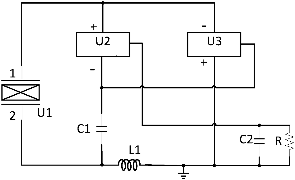
[0011] Such as figure 1 As shown, a piezoelectric vibration energy collection circuit includes a piezoelectric sheet U1, a positive peak detection module U2, a negative peak detection module U3, a first inductor L1, a first energy storage capacitor C1, a second energy storage capacitor C2 and a load R, the first pin of the piezoelectric film U1, the positive pole of the positive peak detection module U2 and the negative pole of the negative peak detection module U3 are connected, the second pin of the piezoelectric film U1, one end of the first inductor L1 and the first energy storage The negative pole of the capacitor C1 is connected, the negative pole of the positive peak detection module U2, the output terminal of the negative peak detection module U3 and the positive pole of the first energy storage capacitor C1 are connected, the output t...


PUM


Abstract

The invention discloses a piezoelectric vibration energy collecting circuit, characterized in that it comprises a piezoelectric sheet, Positive Peak Detection Module, negative peak detection module, first inductance, first energy storage capacitor, A second energy storage capacitor and load, Pin 1 of the piezoelectric patch. the positive electrode of the positive peak detection module and the negative electrode of the negative peak detection module are connected, Pin 2 of the piezoelectric patch. one end of the first inductor and the negative electrode of the first energy storage capacitor areconnected, the negative electrode of the positive peak detection module, the output terminal of the negative peak detection module and the positive electrode of the first energy storage capacitor areconnected, the output terminal of the positive peak detection module, the positive electrode of the second energy storage capacitor and one end of the load are connected, the other end of the first inductance, the positive electrode of the negative peak detection module, the negative electrode of the second energy storage capacitor and the other end of the load are all grounded; The advantage isthat there are fewer energy dissipation elements in the circuit, which greatly reduces the overall power consumption of the LC loop in the circuit, improves the quality factor of the LC loop, and thusimproves the collection efficiency of piezoelectric vibration energy in the whole circuit.

Description

technical field [0001] The invention relates to an energy collection circuit, in particular to a piezoelectric vibration energy collection circuit. Background technique [0002] Piezoelectric vibration energy collection is a method of collecting vibration energy in the environment by using the piezoelectric effect of piezoelectric materials. Since the output voltage of the piezoelectric sheet is an AC signal, the general electronic equipment is powered by a DC power supply. Therefore, an interface circuit is needed between the piezoelectric sheet and the electronic device, and the conversion of AC voltage to DC voltage is realized through the interface circuit. [0003] The simplest interface circuit is a full-bridge rectifier circuit, but the efficiency of the full-bridge rectifier circuit is very low, so someone proposed a self-powered series synchronous switch energy harvesting circuit, a parallel synchronous switch energy harvesting circuit and a synchronous charge extra...

Claims


Application Information

Patent Timeline
IPC IPC(8): H02J7/34
CPCH02J7/345
Inventor 夏银水王修登李毅施阁陈志栋叶益迭夏桦康
Owner NINGBO UNIV
Why Eureka
Try Eureka