Asphalt smoke treatment system

A flue gas treatment and treatment system technology, applied in the field of asphalt flue gas treatment, can solve the problems of unsatisfactory purification effect and high purification burden of treatment equipment, and achieve ideal and obvious purification effect

Pending Publication Date: 2019-01-18
SANY AUTOMOBILE MFG CO LTD
View PDF0 Cites 2 Cited by
  • Summary
  • Abstract
  • Description
  • Claims
  • Application Information

AI Technical Summary

Problems solved by technology

[0005] The purpose of the present invention is to provide an asphalt fume treatment system, in order to solve the technical problem that the single or one-sided asphalt fume tre

Method used


Image

  • Asphalt smoke treatment system
  • Asphalt smoke treatment system
  • Asphalt smoke treatment system

Examples


Embodiment 1

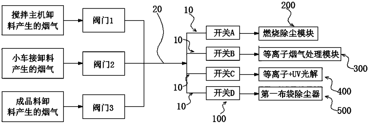
[0036] Such as Figure 1 to Figure 6 As shown, the first embodiment provides an asphalt flue gas treatment system, including: at least two flue gas treatment branches 10 arranged in parallel; each flue gas treatment branch 10 is provided with a switch 100 and a flue gas Processing modules; wherein, at least one flue gas treatment module in the flue gas treatment branch 10 is used to remove flue gas, and at least one flue gas treatment module in the flue gas treatment branch 10 is used to remove dust.

[0037] It should be noted that, in the above-mentioned "at least one flue gas treatment module in the flue gas treatment branch 10 is used to remove flue gas", the flue gas here includes dust-free flue gas and dust-laden flue gas.

[0038]In the bitumen flue gas treatment system of this embodiment, since there are multiple flue gas treatment branches 10, and each flue gas treatment branch 10 is arranged in parallel, each flue gas treatment branch 10 can be Work independently wi...

Embodiment 2

[0070] The second embodiment also provides an asphalt flue gas treatment system, wherein the asphalt flue gas treatment system includes components with the same names and working principles as those in the first embodiment, and its structure is the same as that of the asphalt gas in the first embodiment. The flue gas treatment systems are basically the same, with the differences described below.

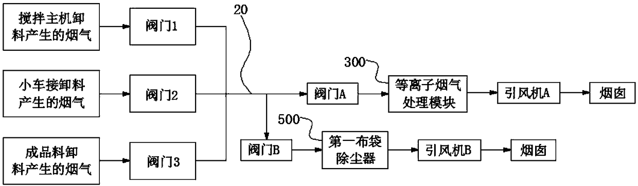
[0071] In this embodiment, along the flow direction of the flue gas, the inlet end of the flue gas treatment branch 10 arranged in parallel is connected to the flue gas output end of the asphalt supply equipment, and the outlet end of the flue gas treatment branch 10 arranged in parallel is connected to the flue.

[0072] Wherein, a main induced fan is provided on the pipeline between the outlet end of the flue gas treatment branch 10 and the flue, and the main induced fan is connected to the chimney through the pipeline. During work, the switch 100 on the working branch is opened, a...

Embodiment 3

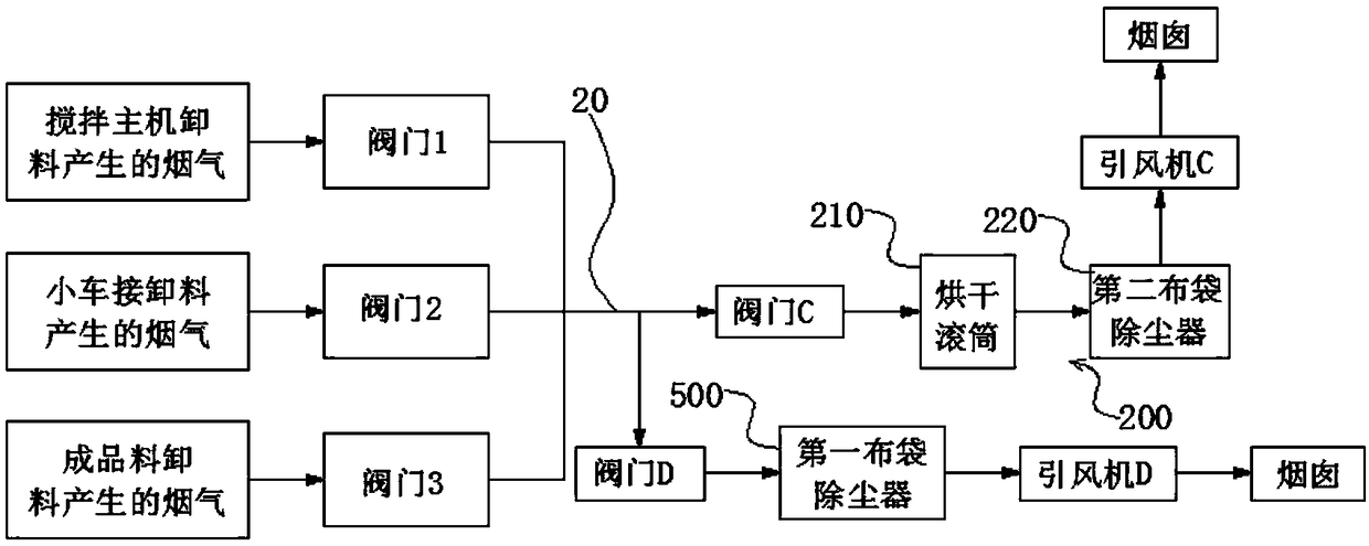
[0074] The third embodiment also provides an asphalt fume treatment system, wherein the asphalt fume treatment system includes parts and components with the same names and working principles as those in the first embodiment, and its structure is the same as that of the asphalt in the first embodiment The flue gas treatment systems are basically the same, with the differences described below.

[0075] For the branch circuit whose flue gas treatment module is set as the plasma flue gas treatment module 300, the flue gas can be sent into the specially designed plasma flue gas treatment module 300, or sent to the existing plasma flue gas treatment of the factory or construction site. Module 300.


PUM


Abstract

The invention provides an asphalt smoke treatment system, which relates to the technical field of asphalt smoke treatment, and aims at solving the technical problems of a single or unilateral asphaltsmoke treatment method adopted by an existing stirring station that the purification burden of a treatment device is easily overhigh, and the purification effect is not ideal. The invention relates tothe asphalt smoke treatment system, which comprises at least two smoke treatment branches which are arranged in parallel connection; each smoke treatment branch is provided with a switch and a smoketreatment module; and the smoke treatment module in at least one smoke treatment branch is used for removing smoke, and the smoke treatment module in the at least one smoke treatment branch is used for removing dust. By adopting the asphalt smoke treatment system, smoke and dust produced in the stirring station can be separately treated, the purification burden of the treatment device is alleviated, and the purification effect is relatively apparent.

Description

technical field [0001] The invention relates to the technical field of asphalt fume treatment, in particular to an asphalt fume treatment system. Background technique [0002] Dust, smoke and other pollution exist in the production and operation of asphalt mixing equipment. In order to coat the asphalt evenly on the stone surface, form a thick and consistent oil film, and improve the road performance of the asphalt mixture, the asphalt is usually heated to 140-160°C or even higher. [0003] Since the discharge temperature of the asphalt mixture is also within the corresponding range of 140-160°C, the finished asphalt mixture formed after stirring will emit a large amount of asphalt fume during the process of unloading and receiving the material from the transport truck. The fume contains A variety of organic substances, including carbocyclic hydrocarbons, cyclic hydrocarbon derivatives and other compounds, such as polycyclic aromatic hydrocarbons such as benzopyrene, benzan...

Claims


Application Information

Patent Timeline
IPC IPC(8): B01D53/32B01D53/02B01D50/00F23G7/06
CPCB01D53/02B01D53/32F23G7/06B01D50/60
Inventor 赵雄王艳军舒乐华
Owner SANY AUTOMOBILE MFG CO LTD
Why Eureka
Try Eureka