Reutilization device for building waste

A construction waste and box technology, applied in grain processing and other directions, can solve the problems of incomplete crushing, short service life, and reduced screening efficiency.

Pending Publication Date: 2019-01-18
禹州金科再生资源有限公司
View PDF0 Cites 5 Cited by
  • Summary
  • Abstract
  • Description
  • Claims
  • Application Information

AI Technical Summary

Problems solved by technology

[0002] During the construction process, a lot of construction waste will be generated. If the waste is discarded, it will occupy a large amount of land resources and cause pollution. If these construction demolition objects can be reused, the high cost of handling will be avoided, and the cost will be saved. It can be remade into concrete and reused. The existing construction waste is crushed and reused without classifying the construction waste. The garbage bags in the construction waste will be wrapped around the crushing roller or the crushing shaft to make it stuck. The metal in it will damage the crushing roller or the crushing shaft, the crushing device is seriously damaged, the service life is short, and the crushing is not thorough. Therefore, it is urgent to design a construction waste treatment device with classification treatment, good crushing effect, prolonging the service life of the crushing device and high crushing efficiency

Method used


Image

  • Reutilization device for building waste
  • Reutilization device for building waste
  • Reutilization device for building waste

Examples


Embodiment 1

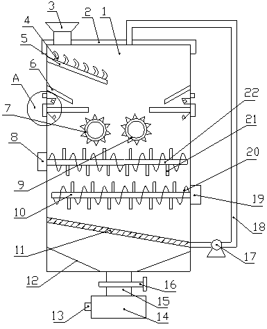
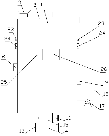
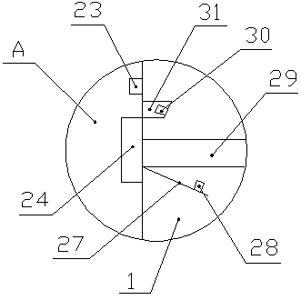
[0022] Such as Figure 1-6 As shown, a construction waste recycling device includes a box body 1, the upper end of the box body 1 is connected with a box cover 2, and the left side of the upper end of the box cover 2 is connected with a feed hopper 3, and the upper end of the box cover 2 is connected with a feed hopper 3, and the upper end of the box The hopper 3 passes through the box cover 2 and communicates with the box body 1. The upper part of the inner wall on the left side of the box body 1 is fixedly connected with an inclined plate 5, and the upper end of the inclined plate 5 is fixedly connected with a hook 4. The box body 1 Electromagnets 6 are symmetrically connected to the inner walls on the left and right sides. The electromagnets 6 are located below the inclined plate 5. Electromagnetic relays 23 are symmetrically installed on the left and right side walls of the box body 1. The left and right inner walls of the box body 1 Symmetrically connected with an electri...

Embodiment 2

[0025] Such as Figure 1-6 As shown, a construction waste recycling device includes a box body 1, the upper end of the box body 1 is connected with a box cover 2, and the left side of the upper end of the box cover 2 is connected with a feed hopper 3, and the upper end of the box cover 2 is connected with a feed hopper 3, and the upper end of the box The hopper 3 passes through the box cover 2 and communicates with the box body 1. The upper part of the inner wall on the left side of the box body 1 is fixedly connected with an inclined plate 5, and the upper end of the inclined plate 5 is fixedly connected with a hook 4. The box body 1 Electromagnets 6 are symmetrically connected to the inner walls on the left and right sides. The electromagnets 6 are located below the inclined plate 5. Electromagnetic relays 23 are symmetrically installed on the left and right side walls of the box body 1. The left and right inner walls of the box body 1 Symmetrically connected with an electri...


PUM


Abstract

The invention discloses a reutilization device for building waste. The reutilization device comprises a tank body, wherein an inclined plate is connected to the upper part of the inner wall of the left side of the tank body, a hanger is connected to the upper end of the inclined plate, electromagnets are connected to the inner walls of the left and right sides of the tank body, a driving motor A and a driving motor B are connected to the middle of the front end surface of the tank body, a crushing shaft A and a crushing shaft B are respectively connected to output shafts of the driving motor Aand the driving motor B, a crushing roll A and a crushing roll B are respectively connected to the other ends of the crushing shaft A and the crushing shaft B, a first motor and a second motor are respectively connected to the middles of the left and right side walls of the tank body, a first crushing shaft and a second crushing shaft are respectively connected to output shafts of the first motorand the second motor, and spiral blades and crushing blades are connected to the first crushing shaft and the second crushing shaft. The reutilization device has the advantages that the classified processing is realized, the crushing effect is good, the service life of a crushing device is prolonged, and the crushing efficiency is high.

Description

technical field [0001] The invention relates to the technical field of construction waste treatment equipment, in particular to a construction waste recycling device. Background technique [0002] During the construction process, a lot of construction waste will be generated. If the waste is discarded, it will occupy a large amount of land resources and cause pollution. If these construction demolition objects can be reused, the high cost of handling will be avoided, and the cost will be saved. It can be remade into concrete and reused. The existing construction waste is crushed and reused without classifying the construction waste. The garbage bags in the construction waste will be wrapped around the crushing roller or the crushing shaft to make it stuck. The metal in it will damage the crushing roller or the crushing shaft, the crushing device is seriously damaged, the service life is short, and the crushing is not thorough. Therefore, it is urgent to design a constructio...

Claims


Application Information

Patent Timeline
IPC IPC(8): B02C18/14B02C18/18B02C4/08B02C23/08B02C18/16B02C18/22
CPCB02C4/08B02C18/0084B02C18/142B02C18/16B02C18/18B02C18/2216B02C23/08B02C2201/06
Inventor 王均召楚小远朱来松
Owner 禹州金科再生资源有限公司
Why Eureka
Try Eureka