Grinding cutter and food waste processor

A technology of knives and cutterheads, applied in the fields of grinding knives and food waste disposers, can solve the problems of reducing grinding efficiency, bad feeling, disharmony, etc., and achieve the effect of improving grinding effect, increasing residence time, and reducing abnormal risk

Pending Publication Date: 2019-01-18
DONGGUAN JIEMEI ELECTRIC APPLIANCE
View PDF13 Cites 2 Cited by
  • Summary
  • Abstract
  • Description
  • Claims
  • Application Information

AI Technical Summary

Problems solved by technology

In daily life, kitchen waste accounts for a considerable proportion of domestic waste, such as melon shells, leftovers, etc.; these kitchen wastes are extremely perishable, produce peculiar smells, and breed bacteria, which are harmful to the living environment and health of the family. have a certain impact
[0003] The types of food waste that the grinding tool faces are messy, including hard waste such as bones. This kind of hard waste is easy to insert into the gap between the relative moving parts and follow the movement during the crushing process, which seriously reduces the The efficiency of crushing will also produce discordant noises. Since the environment for grinding knives is a home kitchen, this kind of noise will give users a very bad feeling

Method used


Image

  • Grinding cutter and food waste processor
  • Grinding cutter and food waste processor
  • Grinding cutter and food waste processor

Examples


Embodiment 1

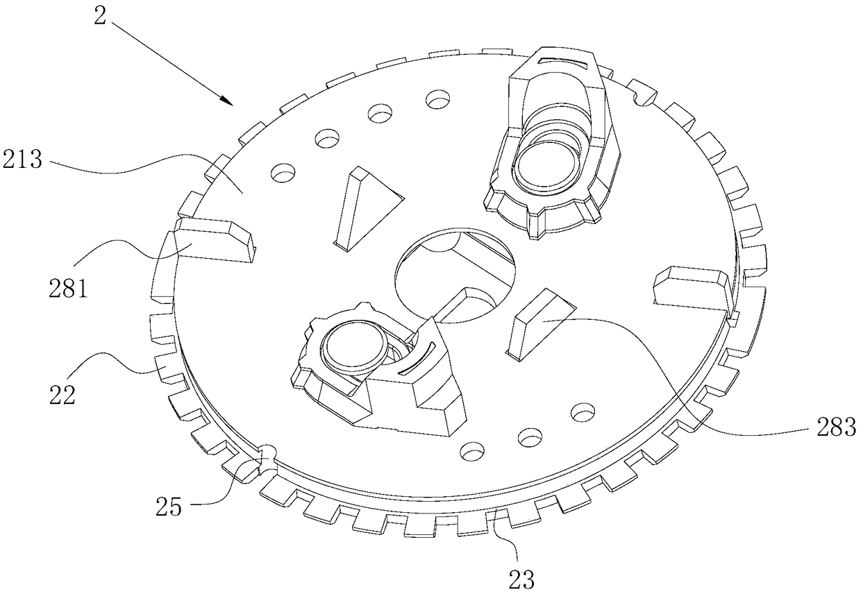
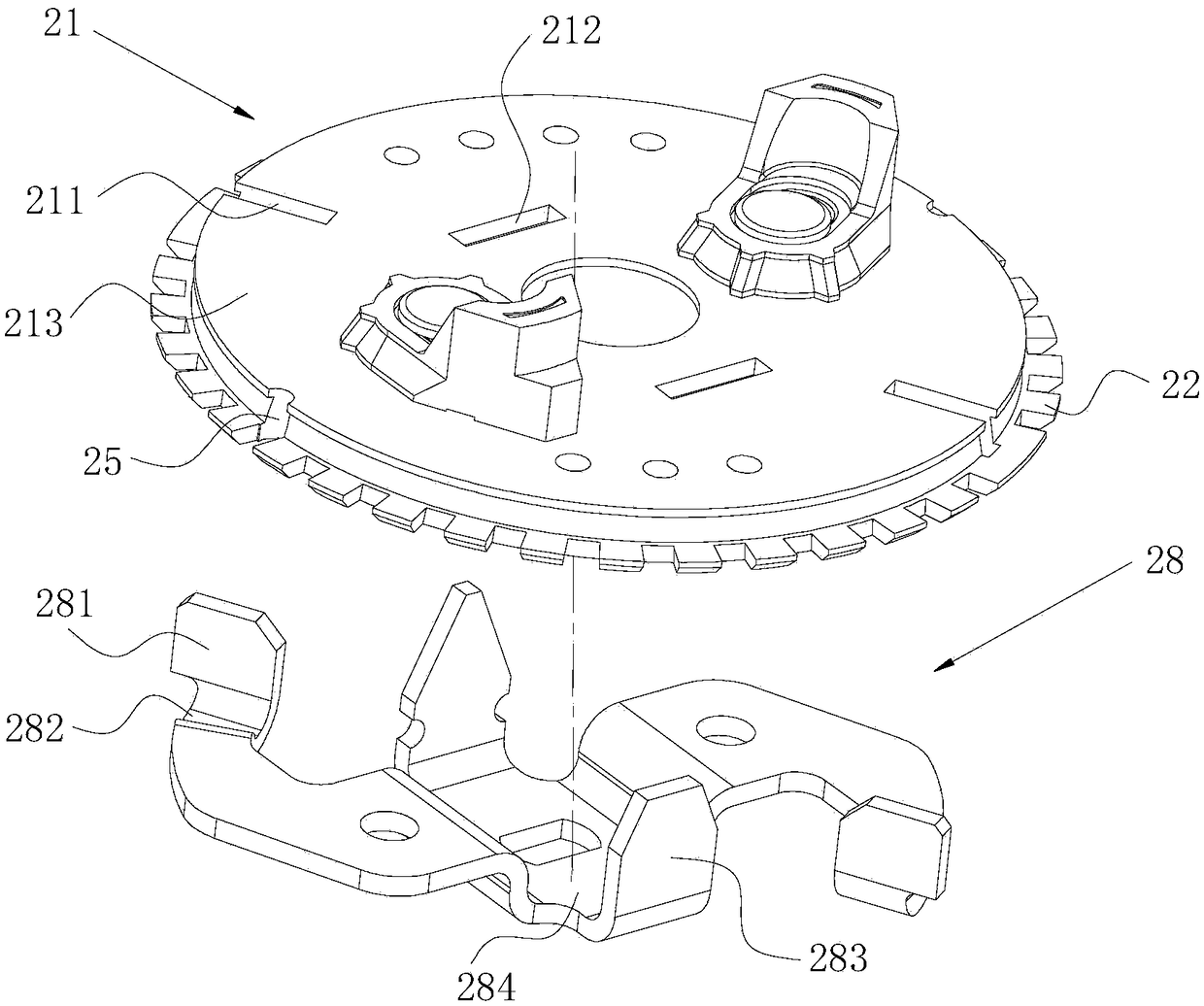
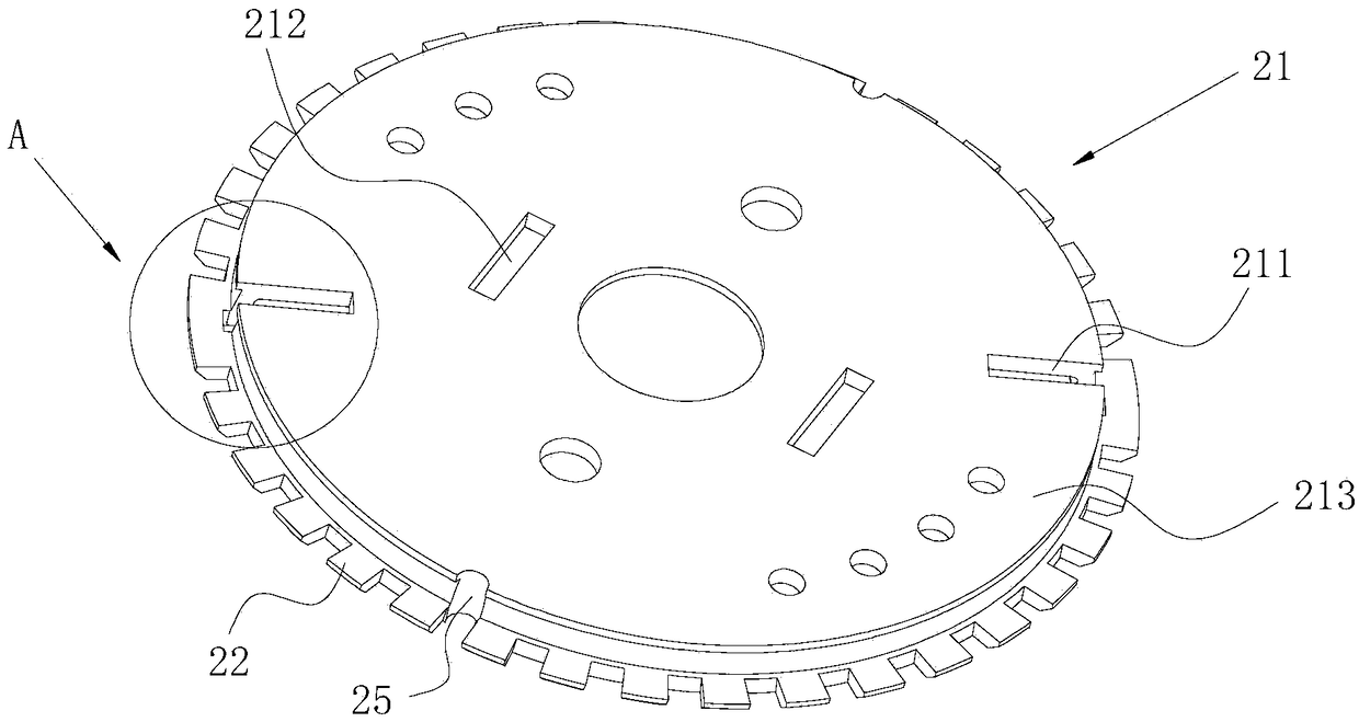
[0066] like Figure 1 to Figure 7 As shown, a grinding tool includes a fixed knife wall 1 and a rotating cutter head 2 installed at the inner lower end of the fixed knife wall 1. The rotating cutter head 2 includes a main body 21 and is arranged on the side wall of the main body 21. A plurality of working teeth 22, the working teeth 22 are arranged at equal intervals on the side wall of the main body 21, the working teeth 22 are located below the fixed knife wall 1, and between adjacent working teeth 22 An interdental boss 23 is arranged in the hollow part of the body, and the interdental boss 23 is formed extending radially outward along the side wall of the main body 21 . By arranging the interdental bosses 23, larger food waste particles can be prevented from directly passing through the gap between the rotating cutter head 2 and the fixed knife wall 1, thereby increasing the flow of food waste particles between the rotating cutter head 2 and the fixed knife wall 1. The re...

Embodiment 2

[0076] The difference between this embodiment and Embodiment 1 is:

[0077] like Figure 8 As shown, the line connecting the first corner line 231 of the interdental boss 23 and the edge of the top surface 213 of the main body 21 passes through the fixed knife wall 1. Such an overall design can ensure that food waste cannot be inserted into the fixed knife wall in a straight line. The gap between the above-mentioned working teeth 22 can more reliably reduce the abnormal risk of food waste being inserted into the gap between the working teeth 22 and rotate with the rotating cutterhead 2, thereby improving the crushing efficiency and reducing the risk of grinding. noise.

Embodiment 3

[0079] The difference between this embodiment and Embodiment 1 is:

[0080] like Figure 9 As shown, the upper surface of the annular groove 26 is inclined upward along the radially outward direction, and the distance between the outer edge of the upper surface of the annular groove 26 and the top surface 213 of the main body 21 is 1mm. Such a design can reduce the distance between the outer edge of the upper surface of the annular groove 26 and the top surface 213 of the main body 21, which is conducive to improving the shearing effect and efficiency of the suspended boss 27 on food waste, and can simultaneously Ensure that the root of the suspended boss 27 has good strength to avoid fracture.

[0081] In other embodiments, the distance between the outer edge of the upper surface of the annular groove and the top surface of the main body may also be 0.8 mm or 0.9 mm or 1.1 mm or 1.2 mm or 1.3 mm or 1.4 mm or 1.5 mm mm.

[0082] The "first" and "second" in this article are ...


PUM


Abstract

The invention belongs to the technical field of kitchen appliances and discloses a grinding cutter comprising a fixed cutter wall and a rotary cutterhead mounted at the lower end of the inside of thefixed cutter wall; the rotary cutterhead comprises a main body and a plurality of working teeth arranged on the side wall of the main body; a hollowed part between every two adjacent working teeth isinternally provided with an intertooth boss; and the intertooth boss is formed by radially and outwards extending along the side wall of the main body. The invention further provides a food waste processor with the grinding cutter. According to the scheme, due to the arrangement of the intertooth bosses on the hollowed parts located among the working teeth, the abnormal risk that food wastes are inserted into the hollowed parts among the working teeth and rotate together with the rotary cutterhead is effectively reduced, so that the smashing efficiency is increased, and noise in a grinding process is reduced.

Description

technical field [0001] The invention relates to the technical field of kitchen appliances, in particular to a grinding knife and a food waste disposer. Background technique [0002] With the improvement of living standards, electrical equipment has become popular in each of our families, especially food waste disposers, which are easy to use and have been widely used in our lives. In daily life, kitchen waste accounts for a considerable proportion of domestic waste, such as melon shells, leftovers, etc.; these kitchen wastes are extremely perishable, produce peculiar smells, and breed bacteria, which are harmful to the living environment and health of the family. have a certain impact. [0003] The types of food waste that the grinding tool faces are messy, including hard waste such as bones. This kind of hard waste is easy to insert into the gap between the relative moving parts and follow the movement during the crushing process, which seriously reduces the The efficienc...

Claims


Application Information

Patent Timeline
Patent Type & Authority Applications(China)
IPC IPC(8): B02C18/18
CPCB02C18/182
Inventor 梁孝峰向荣
Owner DONGGUAN JIEMEI ELECTRIC APPLIANCE
Why Eureka
Try Eureka