Reinforcing steel bar bending machine with conveying mechanism

A conveying mechanism and bending machine technology, applied in metal processing equipment, grinding/polishing equipment, grinding machines, etc., can solve the problems of reduced bending efficiency of steel bars, inability to remove rust on the surface of steel bars, etc. The effect of low cost and improved work efficiency

Active Publication Date: 2019-01-18
JIANGSU RUINENG ELECTRIC POWER EQUIP
View PDF9 Cites 3 Cited by
  • Summary
  • Abstract
  • Description
  • Claims
  • Application Information

AI Technical Summary

Problems solved by technology

[0005] The object of the present invention is to provide a steel bar bending machine provided with a conveying mechanism to solve the problem that the existing bending machine proposed in the background art cannot effectively remove the rust on the surface of the steel bar during actual use; If the personnel manually place the subsequent steel bars into the bending mechanism on the bending machine, the bending efficiency of the steel bars will be reduced.

Method used


Image

  • Reinforcing steel bar bending machine with conveying mechanism
  • Reinforcing steel bar bending machine with conveying mechanism
  • Reinforcing steel bar bending machine with conveying mechanism

Examples


Embodiment Construction

[0025] The technical solutions in the embodiments of the present invention will be clearly and completely described below in conjunction with the accompanying drawings in the embodiments of the present invention. Obviously, the described embodiments are only a part of the embodiments of the present invention, rather than all the embodiments. Based on the embodiments of the present invention, all other embodiments obtained by those of ordinary skill in the art without creative work shall fall within the protection scope of the present invention.

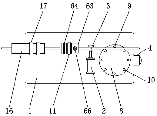
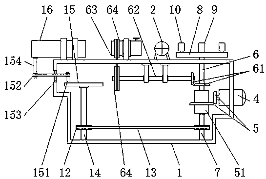
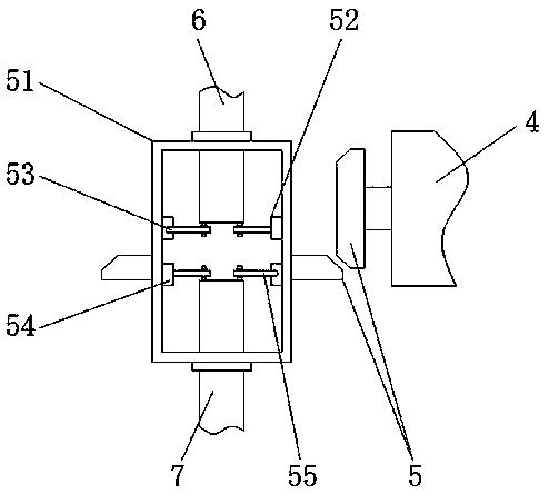
[0026] See Figure 1-8 , The present invention provides a technical solution: a steel bar bending machine equipped with a conveying mechanism, including a frame 1, an electric push rod 2, a cutter 3, a motor 4, a first bevel gear 5, a sleeve 51, a second A ratchet 52, a first pawl 53, a second ratchet 54, a second pawl 55, a first vertical shaft 6, a second bevel gear 61, a horizontal shaft 62, a rust removal cylinder 63, a first pulley ...


PUM


Abstract

The invention discloses a reinforcing steel bar bending machine with a conveying mechanism. The machine comprises an electric push rod, a motor, a bending disc and a bearing pedestal. The electric push rod is installed at the upper end face of a rack, the motor is installed at the side wall of the rack, a second vertical shaft distributed perpendicularly is rotationally installed inside the rack,the bending disc is located at the upper end face of the rack, the bearing pedestal is installed on the rack, a second belt pulley is installed at the lower half section of the second vertical shaft,a horizontally-distributed disc is installed at the top end of a transmission shaft, a sliding ring is fixedly installed at the upper end face of the rack, and a conveying cylinder is slidably connected to the interior of the sliding ring. According to the reinforcing steel bar bending machine with the conveying mechanism, by improving the internal structure of an existing bending machine, the bending machine can more efficiently bend reinforcing steel bars, the functions are more abundant and practical, the whole working efficiency of the bending machine is greatly improved, and the reinforcing steel bar bending quality is improved.

Description

Technical field [0001] The invention relates to the technical field related to hardware, in particular to a steel bar bending machine provided with a conveying mechanism. Background technique [0002] The modern definition of hardware mostly refers to finished parts after metal processing, such as steel bars. Rebar is the most basic and most important hardware component in construction sites. Because of different usage requirements, the requirements for the use of steel bars are different, so Before the actual use of the steel bars, most of them will use the bending machine to bend the steel bars into a specified shape. The existing steel bar bending machines are actually operated by hydraulic or electric motors as the power source, and directly bend the steel bars gradually into the specified shape. The shape and internal structure design are too simple, resulting in poor bending effect. Therefore, the existing bending machine still has the following problems in actual use: [00...

Claims


Application Information

Patent Timeline
Patent Type & Authority Applications(China)
IPC IPC(8): B21F1/00B21F11/00B21F23/00B24B27/033
CPCB21F1/00B21F11/00B21F23/00B24B27/033
Inventor 侯潇莹
Owner JIANGSU RUINENG ELECTRIC POWER EQUIP
Why Eureka
Try Eureka