Rotary centrifugal multi-blade cutting machine

A rotary centrifugal and cutting machine technology, applied in metal processing and other directions, can solve the problems of complex transmission system structure, high cost of machinery and equipment, and high precision of parts manufacturing, and achieve the effects of low cost, good cutting quality, and improved work efficiency.

Inactive Publication Date: 2019-01-18
CHINA UNIV OF MINING & TECH
View PDF6 Cites 14 Cited by
  • Summary
  • Abstract
  • Description
  • Claims
  • Application Information

AI Technical Summary

Problems solved by technology

However, the action of the entire cutting process is completed by two mechanisms, so the structure of the transmission system is complicated, resulting in high cost of machine equipment, high precision of parts manufacturing, and difficult operation. At the same time, the cutter is installed on the cutter holder, and it is difficult to replace the blade after it is damaged.

Method used


Image

  • Rotary centrifugal multi-blade cutting machine
  • Rotary centrifugal multi-blade cutting machine
  • Rotary centrifugal multi-blade cutting machine

Examples


Embodiment Construction

[0025] Embodiments of the invention will be described in detail below with reference to the accompanying drawings. The description of the embodiments is for the purpose of illustration only, and in no way limits the invention and its application or use.

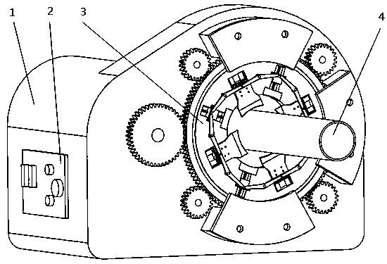
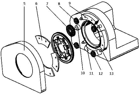
[0026] Such as figure 1 and figure 2 As shown, the rotary centrifugal multi-blade cutting machine provided by the present invention is used for pipe cutting. The cutting machine includes: a machine base 1, a control panel 2 arranged on the side of the machine base 1, a dust cover 5, and a cutting unit 3; The panel 2 is used to control the operation of the motor inside the machine base. The motor provides power for the cutting machine. The motor spindle 10 is exposed outside the end surface of the machine base 1; the end surface of the machine base 1 has a circular channel, which is convenient for the pipe 4 to enter the cutting unit 3 Cutting; the dust cover 5 is used to prevent dust and cuttings from entering the meshing ...


PUM


Abstract

The invention relates to the field of pipe material feeding, in particular to a rotary centrifugal multi-blade cutting machine. The machine comprises a machine base and a cutting unit; the machine base comprises a motor, a control panel, a driving gear, an auxiliary gear, a supporting gear and a supporting bearing; the cutting unit comprises a gear cutter head, a knife seat mechanism, a centrifugal mechanism and a connecting rod, various sliding grooves are formed in the surface of the gear cutter head for respectively mounting the knife seat mechanism and the centrifugal mechanism, the knifeseat mechanism includes a base, a cutter head sliding block, a blade, a return spring, a limit block and the like, the cutter head sliding block is connected to the base through a sliding through, a circular groove formed in the middle after connection is used for mounting the spring, and the connecting rod is connected to the cutter head sliding block and the centrifugal mechanism. The structureof the machine is simple, only a single motor is required to drive the cutter head to rotate, the centrifugal force of the centrifugal mechanism is converted into the axial cutting force of the bladeduring the rotary cutting process, no other power is provided, the blade replacement is convenient, the contact area of the annular blade and a pipe material is large, and the quality of the incisionis ensured.

Description

technical field [0001] The invention relates to a pipe material cutting tool, in particular to a rotary centrifugal multi-blade cutting machine. Background technique [0002] At present, most of the pipe cutting operations at home and abroad are completed by using grinding wheels or saw blades. Although the cutting speed of the grinding wheel saw is fast, the cutting accuracy is low. During the process of cutting metal pipes, a large number of sparks will be generated, and burrs or flashes are likely to be generated at the incision of the pipe. If the pipe with a larger diameter is cut, the pipe may be broken. The grinding wheel saw machine usually uses a motor to drive the saw blade to rotate, and the tangential force is provided by manpower. It is difficult to provide a suitable tangential force during the cutting process. Excessive tangential force will affect the shape of the pipe. If the tangential force is too high If it is small, it will take a long time to cut and a...

Claims


Application Information

Patent Timeline
IPC IPC(8): B26D1/29B26D3/16B26D7/26B26D5/08
CPCB26D1/29B26D3/16B26D5/08B26D7/2614
Inventor 李中凯殷文卫苗磊刘等卓
Owner CHINA UNIV OF MINING & TECH
Why Eureka
Try Eureka