
Pneumatic false beam assembly structure for foaming mould of refrigerator box

A foaming mold and false beam technology is applied in the field of the pneumatic false beam tooling structure of the refrigerator box foaming mold, which can solve the problems of fast running speed, damage to the box foaming mold, and scrapping and scrapping of the box body foaming. Improve the level of automation, reduce daily processing, and solve the effect of labor costs

Pending Publication Date: 2019-01-18
CHANGHONG MEILING CO LTD
View PDF4 Cites 5 Cited by
  • Summary
  • Abstract
  • Description
  • Claims
  • Application Information

AI Technical Summary

Problems solved by technology

[0002] At present, in the refrigerator industry, when producing refrigerators with false beam structures, the production method of manually picking and placing false beam tooling is generally adopted in the box pre-assembly and foaming process sections, which increases the labor intensity of employees on the one hand in the actual production process On the other hand, due to the fast running speed of the line body and the large number of fixed lining mold tapes, there are artificially installed lining molds that are not firm, fall off, and skewed, resulting in quality defects such as foaming, crushing, scrapping, and galling of the box. In severe cases, it will cause Damage to the box foaming mold

Method used


Image

  • Pneumatic false beam assembly structure for foaming mould of refrigerator box
  • Pneumatic false beam assembly structure for foaming mould of refrigerator box
  • Pneumatic false beam assembly structure for foaming mould of refrigerator box

Examples


Embodiment Construction

[0033] In order to make the purposes, technical solutions and advantages of the embodiments of the present invention clearer, the technical solutions in the embodiments of the present invention will be clearly and completely described below in conjunction with the embodiments of the present invention. Obviously, the described embodiments are part of the present invention. examples, but not all examples. Based on the embodiments of the present invention, all other embodiments obtained by those of ordinary skill in the art without creative efforts shall fall within the protection scope of the present invention.

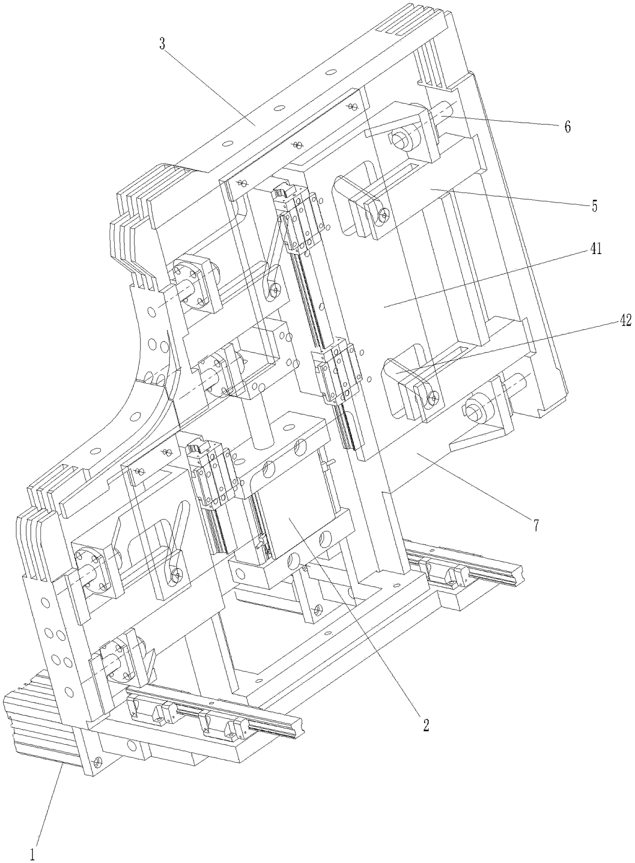
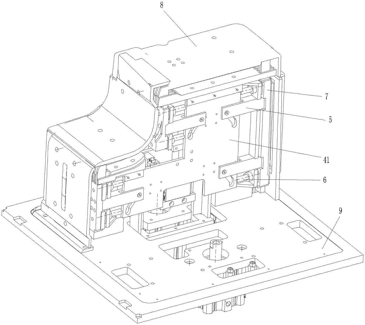
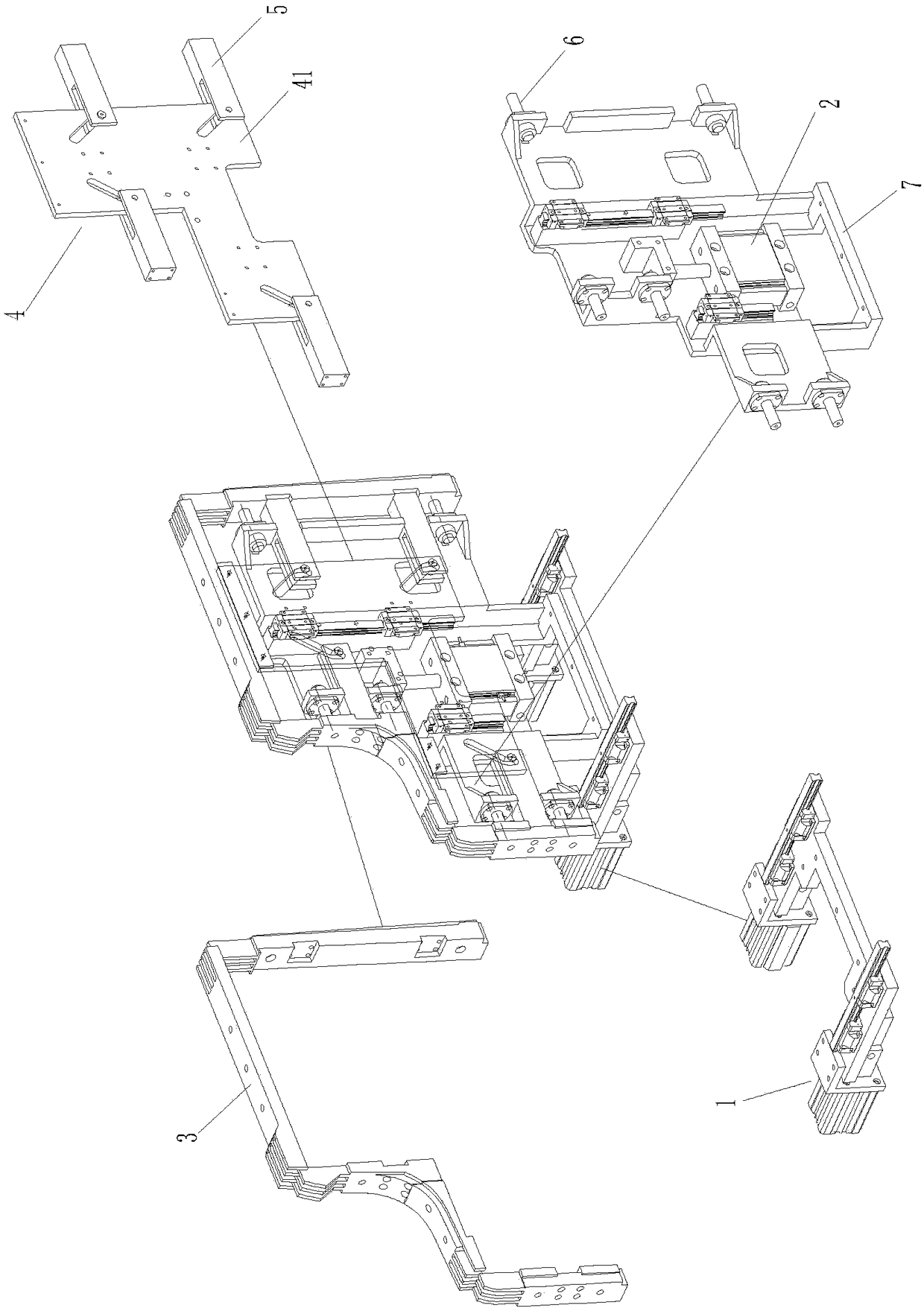
[0034] Please refer to figure 1 8, the structure of the pneumatic false beam tooling structure of the refrigerator box foaming mold of the present embodiment is set as follows:

[0035] The external motion cylinder 11 and the external slide rail 12 constitute the external motion component 1, which is fixed on the box foaming fixture hanger 9, and the mechanism integral...


PUM


Abstract

The invention provides a pneumatic false beam assembly structure for a foaming mould of a refrigerator box. Compressed air is taken as a power source; an existing signal of a box foaming clamp is utilized to control a cylinder to open and close, so as to realize automatic expansion and contraction of a pneumatic false beam assembly; the motion mode of false beam is divided into inner and outer modes; an external motion cylinder and an external slide rail are formed into an external motion component and are fixedly arranged on a hanging bracket of the box foaming clamp; an overall mechanism fixing frame is arranged on the external motion component; the external motion component is adopted for finishing the overall exterior motion of the false beam; an internal motion cylinder and an internal slide rail of an internal motion component are arranged on the overall mechanism fixing frame; a false beam motion plate of a false beam motion component is pushed by the internal motion component to drive a false beam expansion and contraction component to finish the interior motion. According to the invention, full automatic pneumatic false beam assembly is realized, the working mode of manually placing the false beam assembly in the preassembled stage of the box is replaced and the function of quickly assembling and disassembling during the processes of online production and routine maintenance is achieved.

Description

technical field [0001] The invention relates to a tooling structure, in particular to a pneumatic false beam tooling structure for a refrigerator box body foaming mold. Background technique [0002] At present, in the production of refrigerator products with false beam structure in the refrigerator industry, the production method of manually picking and placing false beam tooling is generally adopted in the pre-installation and foaming process of the box, which increases the labor intensity of employees in the actual production process on the one hand. On the other hand, due to the fast running speed of the line body and the large number of fixed liner tapes, there are artificially installed liner molds that are not firmly detached and skewed, resulting in quality defects such as box foaming, folding, scrapping, and gallbladder. Damage to the box foaming mold. In addition, with the increase in the cost of human resources, the automation and de-manualization of the refrigera...

Claims


Application Information

Patent Timeline
Patent Type & Authority Applications(China)
IPC IPC(8): B29C44/58
CPCB29C44/58B29L2031/7622
Inventor 黄荷坤权传斌
Owner CHANGHONG MEILING CO LTD
Learn More