Quasi-elliptical airfoil for high-speed helicopter rotor reflux region
A helicopter rotor, ellipse-like technology, applied in the directions of rotorcraft, motor vehicles, aircraft, etc., can solve the problems of inability to adapt to high-speed helicopters, large airfoil resistance, etc., and achieve the goal of suppressing flow separation, high aerodynamic efficiency, and improving cruise efficiency. Effect
Active Publication Date: 2019-01-18
NORTHWESTERN POLYTECHNICAL UNIV
View PDF5 Cites 3 Cited by
- Summary
- Abstract
- Description
- Claims
- Application Information
AI Technical Summary
Problems solved by technology
[0005] In the above scheme, although the use of standard elliptical airfoils can alleviate some adverse aerodynamic phenomena in the rotor reflux zone, the airfoil is not specially designed for the flow characteristics of the rotor reflux zone, and cannot meet the needs of high-speed helicopters
The DBLN526 airfoil used on the
Method used
View moreImage
Smart ImageViewing Examples
Examples
 PUM
 Abstract
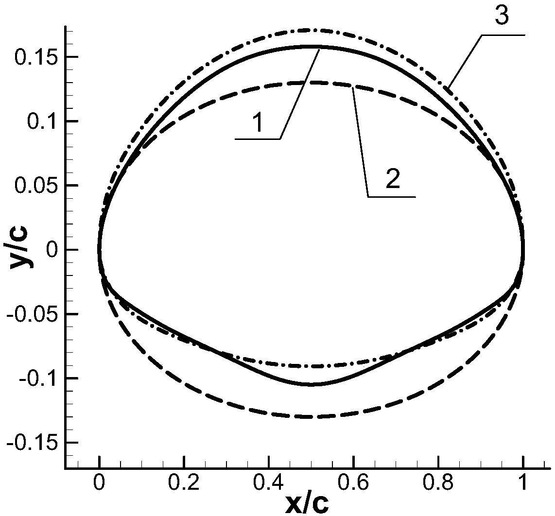
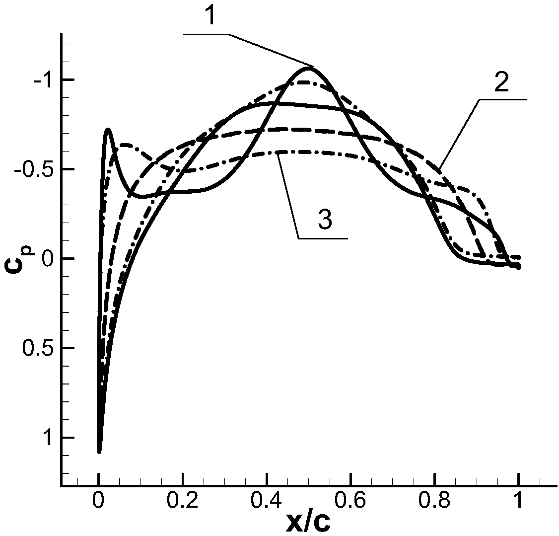
The present invention provides a quasi-elliptical airfoil for a high-speed helicopter rotor reflux region. The airfoil is a blunt trailing edge airfoil with symmetrical front and rear. The leading edge radius of the upper surface of the airfoil is 0.0385, the leading edge radius of the lower surface of the airfoil is 0.0230, the trailing edge radius of the upper surface of the airfoil is 0.0385, and the trailing edge radius of the lower surface of the airfoil is 0.0230. The maximum thickness of the airfoil is 26% C, the maximum thickness is 50% C and the curvature is 2.8% C. The lower surfaceof the airfoil has some concavity near the leading edge and the trailing edge, so that the lift of the airfoil is improved. The invention has the advantages that the quasi-elliptical airfoil applied to the rotor reflux region of a high-speed helicopter designed according to the actual flow characteristics of the reflux region has smaller resistance of the reflux region, higher aerodynamic efficiency and can effectively suppress the flow separation phenomenon, thereby improving the cruise efficiency of the helicopter and meeting the requirements of a new generation of high-speed helicopter.
Description
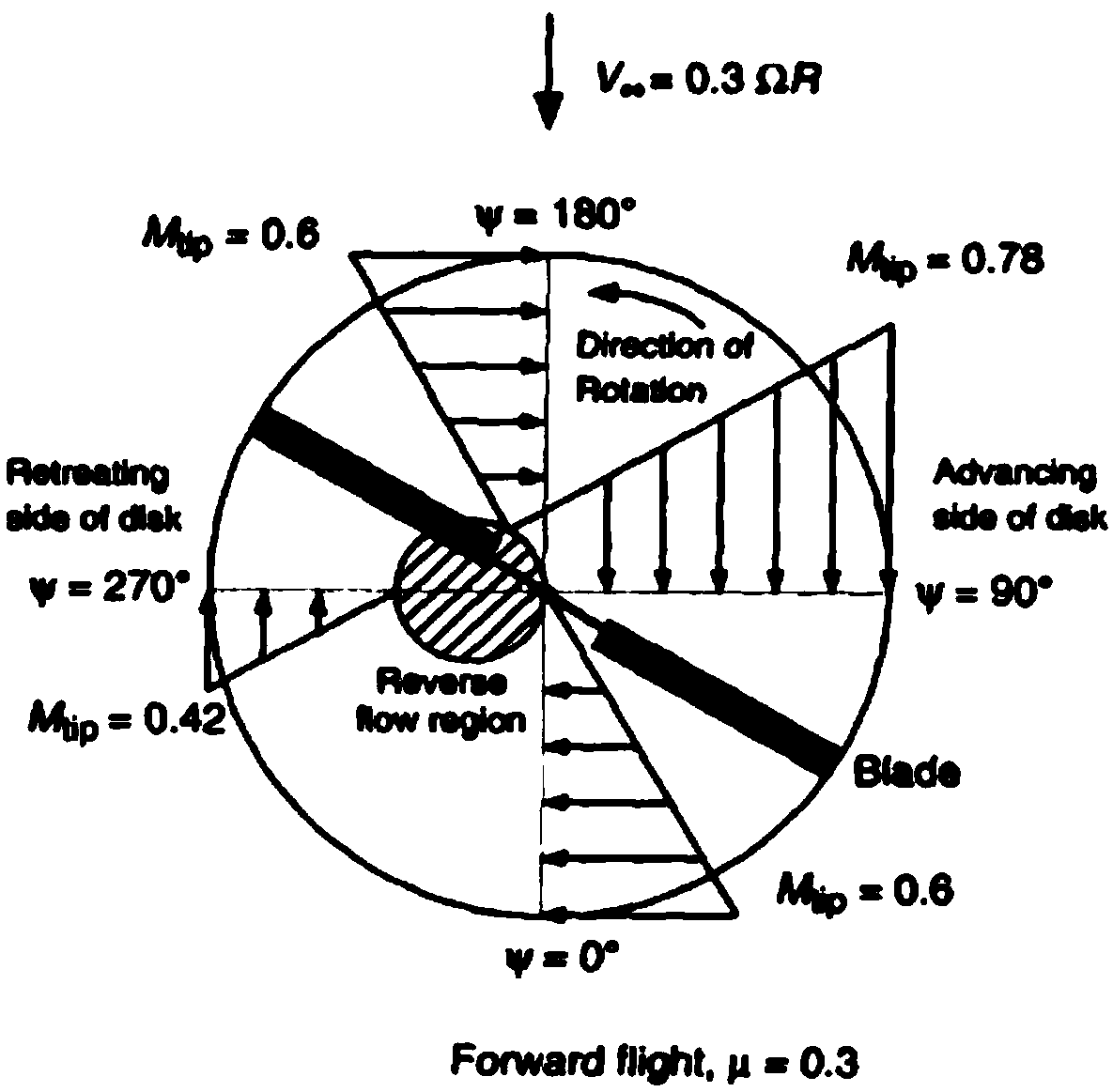
technical field [0001] The invention belongs to the technical field of airfoil design, and in particular relates to a quasi-elliptical airfoil applied to the reflux area of a high-speed helicopter rotor. Background technique [0002] When the helicopter is flying forward with a certain forward ratio μ, due to the superimposed effect with the incoming flow, the relative airflow velocities between the forward blade area and the backward blade area of the rotor are asymmetric. When the relative radius r in the area of the backward blade is smaller than μR|sinψ|, there will be a phenomenon that the relative airflow blows from the rear edge to the front edge. The area where this phenomenon exists is called the "reflux area", such as figure 1 indicated by the circular shaded area. The aerodynamic efficiency of the blade in the reflux zone is low, there is a serious flow separation phenomenon, and it is prone to stall. [0003] The coaxial rigid rotor is the key component o...
Claims
Login to View More Application Information
Patent Timeline
 IPC IPC(8): B64C27/467B64C27/473
CPCB64C27/467B64C27/473
Inventor 赵佳祥宋文萍韩忠华韩少强聂晗许建华
Owner NORTHWESTERN POLYTECHNICAL UNIV
Features
- R&D
- Intellectual Property
- Life Sciences
- Materials
- Tech Scout
- Unparalleled Data Quality
- Higher Quality Content
- 60% Fewer Hallucinations
Learn More Browse by: Latest US Patents, China's latest patents, Technical Efficacy Thesaurus, Application Domain, Technology Topic, Popular Technical Reports.
© 2025 PatSnap. All rights reserved.Legal|Privacy policy|Modern Slavery Act Transparency Statement|Sitemap|About US| Contact US: help@patsnap.com


