UAV slideway type air quick recovery system

A recovery system and machine slide rail technology, applied in the field of drones, can solve problems such as the inability to recover multiple swarm drones at one time, the inability to adapt to the rapid recovery of small drones, and the risk of transport aircraft safety. , to achieve the effect of ensuring the success rate of docking, high docking success rate and preventing structural damage

Active Publication Date: 2019-01-18
NORTHWESTERN POLYTECHNICAL UNIV
View PDF8 Cites 4 Cited by
  • Summary
  • Abstract
  • Description
  • Claims
  • Application Information

AI Technical Summary

Problems solved by technology

[0005] Due to limiting factors such as size and weight, we cannot simply transport land-based and sea-based UAV recovery devices directly into the air for UAV recovery. They cannot meet the requirements of recovering multiple swarm drones at one time.
Existing aerial recovery devices, such as patent CN 107697303A, adopt the method of single-drag and stable target single-frame recovery. Although this method can realize the aerial recovery of a single UAV, there are unavoidable design defects: first , to ensure the successful docking of small UAVs, it is necessary to ensure the stability of the towed stable target. For uncontrolled targets, the conditions are harsh and it is difficult to guarantee successful docking
Secondly, it can only be recovered by a single drone, and the recovery efficiency is seriously reduced due to repeated retraction and release of the tow cable, which cannot meet the needs of rapid recovery of multiple small drones
Thirdly, the flight speed of the transport aircraft is faster than that of the small drones. Reducing the speed of the transport aircraft poses a risk to the safety of the transport aircraft. It is also difficult to ensure the accuracy of the docking when the drone is flying at full speed, and it is difficult to guarantee the successful docking

Method used


Image

  • UAV slideway type air quick recovery system
  • UAV slideway type air quick recovery system
  • UAV slideway type air quick recovery system

Examples


Embodiment Construction

[0039] The present invention will be described in detail below in conjunction with specific embodiments. The following examples will help those skilled in the art to further understand the present invention, but do not limit the present invention in any form. It should be noted that those skilled in the art can make several modifications and improvements without departing from the concept of the present invention. These all belong to the protection scope of the present invention.

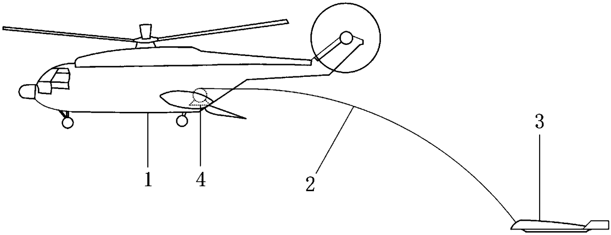
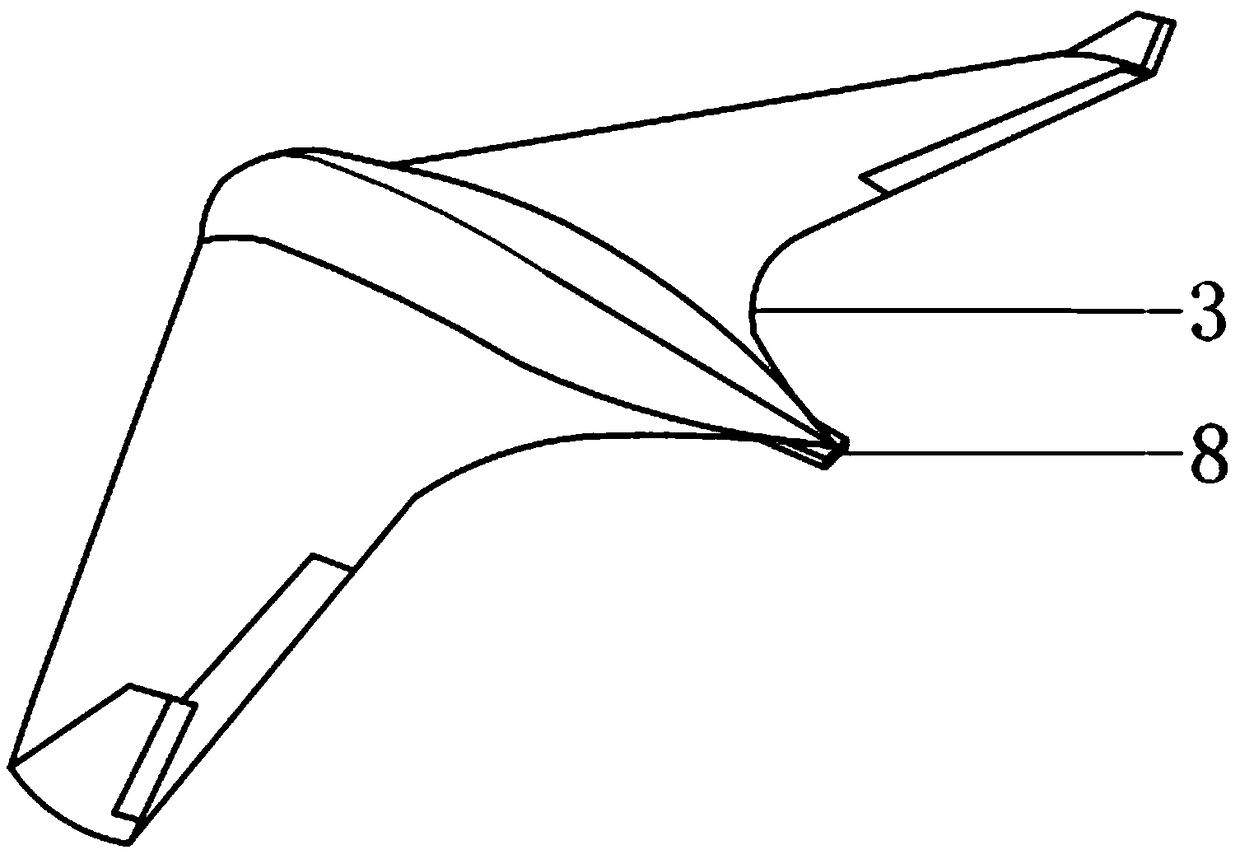
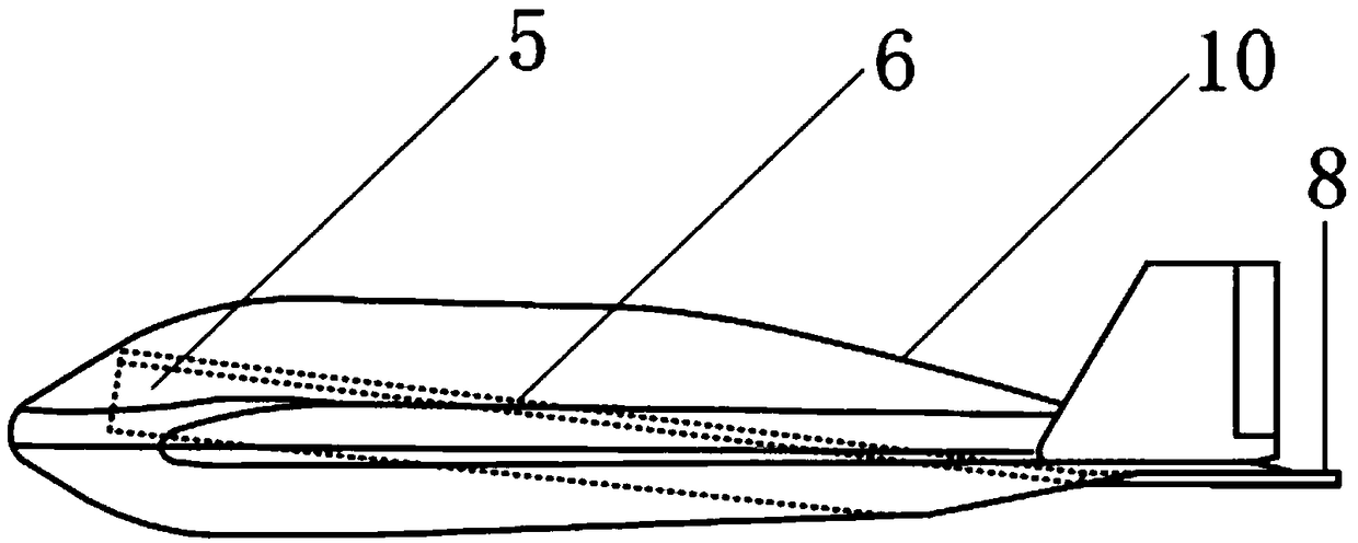
[0040]Such as figure 1 — Figure 9 Shown, a kind of unmanned aerial vehicle sliding track type aerial fast recovery system of the embodiment of the present invention, this unmanned aerial vehicle rapid multi-frame recovery device consists of a carrier aircraft 1, a tow cable 2, a flying wing-shaped towing cabin 3, and an aviation winch 4 Consists of a catch and recovery device for slide rails; the schematic diagram of the flying wing-shaped towing cabin 3 is as follows: figure 2 , image 3 As ...


PUM


Abstract

The invention discloses an unmanned aerial vehicle (UAV) slideway type air quick recovery system, which is composed of a carrier, a towing cable, a flying wing-shaped towing cabin, an aviation winch and a slideway capture and recovery device. At that time of recovery, the tow cable is released through an aeronautical winch, Release the wing-shaped towing module, guided by the guidance system, theUAV approaches the rear of the flying wing-shaped towed cabin, The UAV folds the wing and shuts down, moves along the sliding track into the towing cabin for fixing, and the next catch hook moves to the opposite interface in place through the conveying system. The trap hook of the UAV folds the wing and locks down. After the unmanned aerial vehicle (UAV) to be recovered is fully recovered, the towing cabin of the aviation winch and the unmanned aerial vehicle (UAV) are collected into the carrier aircraft together to complete the air recovery. The invention can quickly recover a plurality of batches of small unmanned aerial vehicles (UAVs), the flying wing-shaped towing cabin in the recovery process is far away from the carrier, the disturbance of the wake flow field of the carrier is small, the safety of the carrier is improved, and the recovery accuracy of the UAV is improved.

Description

technical field [0001] The invention relates to the technical field of unmanned aerial vehicles, in particular to an unmanned aerial vehicle sliding track type air rapid recovery system. Background technique [0002] In recent years, as a brand-new and subversive ideal combat mode, swarm UAV tactics have attracted the attention of various countries. It takes intelligent cluster technology as the core, and connects the weak combat capabilities of single aircraft through the collaborative network of UAVs. Build a new type of combat system with low cost, strong anti-strike capability, and diversified combat modes. [0003] The core advantages of UAV swarms are: low stand-alone cost, large number of swarms, and high swarm intelligence, which means that swarm drones are often designed as disposable consumables. However, even at a low cost, they still contain some unwanted The key core technology mastered by the enemy, one solution is to destroy the drone or damage the electronic...

Claims


Application Information

Patent Timeline
IPC IPC(8): B64D47/00B64D5/00
CPCB64D5/00B64D47/00
Inventor 童小燕吴云皓罗天佑张少江姚磊江张伟杨广珺
Owner NORTHWESTERN POLYTECHNICAL UNIV
Why Eureka
Try Eureka