Automatic butting device and butting method of cast-in-situ bored pile reinforcement cages

A technology of bored cast-in-place piles and docking devices, which is applied to sheet pile walls, buildings, and foundation structure engineering, etc. It can solve the problems of reduced engagement length between steel bar threads and sleeves, slow docking speed, cumbersome operations, etc., and saves machinery. The effect of reducing shift costs, reducing pile-forming time, and improving economic benefits

Active Publication Date: 2019-11-26
NO 1 CONSTR ENG CO LTD OF CHINA CONSTR THIRD ENG BUREAU CO LTD
View PDF6 Cites 2 Cited by
  • Summary
  • Abstract
  • Description
  • Claims
  • Application Information

AI Technical Summary

Problems solved by technology

[0004] When the existing steel cages are docked, it is impossible to ensure that the upper and lower alignment of the connecting steel bars is accurate after the upper and lower steel cages are in place, and there are often deviations. When the upper and lower steel cages are butted, it is inevitable that there will be a gap between the upper and lower ends of the local steel bars, which will reduce the bite length between the steel bar thread and the sleeve, weaken the connection strength at the joint, and cannot guarantee the quality of the joint. Moreover, when the alignment of the connecting steel bars of the upper and lower steel cages is inaccurate, it will also cause cumbersome on-site operations for workers, time-consuming and laborious, and slow docking speed, thereby affecting the construction speed of the pile foundation.

Method used


Image

  • Automatic butting device and butting method of cast-in-situ bored pile reinforcement cages
  • Automatic butting device and butting method of cast-in-situ bored pile reinforcement cages
  • Automatic butting device and butting method of cast-in-situ bored pile reinforcement cages

Examples


Embodiment Construction

[0034] In order to enable those skilled in the art to better understand the technical solution of the present invention, the present invention will be described in detail below in conjunction with the accompanying drawings and specific embodiments.

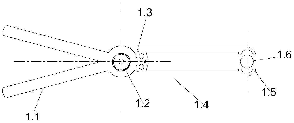
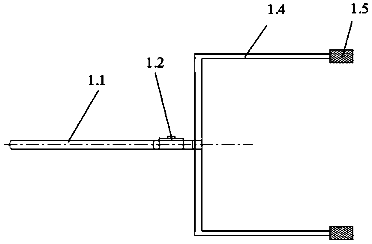
[0035] Such as Figure 1 to Figure 8 As shown, the embodiment of the present invention discloses an automatic docking device for reinforced cages of bored piles, including a clamping part 1, a sleeve and an automatic screwing mechanism 4, and the clamping part 1 includes a scissor arm 1.1, an automatic locking mechanism 1.2 and the clamping mechanism, two scissor arms 1.1 are connected at one end by an automatic locking mechanism 1.2, the central axis of the automatic locking mechanism 1.2 is the scissors shaft (fulcrum), and the automatic locking mechanism 1.2 is a purchased part, which is a rotating The locking mechanism can be locked in reverse and unlocked by itself during the rotation. The clamping mechanism is connected to ...


PUM


Abstract

The invention discloses an automatic butting device and butting method of cast-in-situ bored pile reinforcement cages. The butting method comprises the following steps that firstly, clamping elementsare manufactured; secondly, the reinforcement cages are connected in a butting manner; thirdly, main reinforcement of the upper reinforcement cage is sleeved with a sleeve; fourthly, an automatic screwing mechanism is installed, an outer shell and a driven gear are sequentially opened so that a locking sleeve at the center of a driven gear can tightly wrap the sleeve, then, the driven gear is tightened through a self-locking press-button switch, an upper sliding shell is closed to achieve locking; and fifthly, a play button is started, a driving gear drives the driven gear to rotate until a connection sleeve at the end of the upper reinforcement cage is screwed to the reinforcement end of the lower reinforcement cage, automatic stopping is carried out, and therefore butting of the upper reinforcement cage and the lower reinforcement cage is achieved. According to the automatic butting device and butting method of the cast-in-situ bored pile reinforcement cages, the butting speed of thereinforcement cages and the pile foundation construction speed are accelerated, operation is easy and convenient for workers on the scene, time and labor are saved, the pile-forming time is shortened, cost of a mechanical stage machine-team and the like is saved, the construction period is shortened, and the construction economical benefits are remarkably improved.

Description

technical field [0001] The invention belongs to the technical field of bored pile construction, and in particular relates to an automatic docking device and a docking method for reinforced concrete bored pile reinforcement cages. Background technique [0002] Reinforced concrete cast-in-place piles are currently widely used in foundation treatment projects for housing construction, railways, highway bridges and culverts, and municipal engineering. Among them, the reinforced concrete cast-in-place piles used in the design of railways, highways and municipal bridges and culverts have large pile diameters, large main reinforcement diameters, and relatively large steel bars. Due to the characteristics of high density and long pile body, the weight and length of the reinforced cage made at one time are relatively large, which makes it very difficult to install the reinforced cage at one time, and the safety risk during hoisting is large. Therefore, the construction of longer reinf...

Claims


Application Information

Patent Timeline
Patent Type & Authority Applications(China)
IPC IPC(8): E02D5/34
CPCE02D5/34
Inventor 闫渊董文宝许锋程华敏
Owner NO 1 CONSTR ENG CO LTD OF CHINA CONSTR THIRD ENG BUREAU CO LTD
Why Eureka
Try Eureka