A combined beam beam and hanging beam device and its hoisting method

A combined and hanging beam technology, which is applied in the direction of transportation and packaging, load hanging components, etc., can solve the problems of restricting the integrity of ships or platforms, affecting the construction cycle and cost control of shipyards, and the large amount of legacy work at the wharf. The effect of hoisting requirements

Active Publication Date: 2019-11-08
广州黄船海洋工程有限公司
View PDF8 Cites 0 Cited by
  • Summary
  • Abstract
  • Description
  • Claims
  • Application Information

AI Technical Summary

Problems solved by technology

Usually, the height of this type of structure is high, even exceeding the lifting height of the shipyard’s gantry crane. It needs to be hoisted with the help of a floating crane, which seriously restricts the integrity of the ship or platform before launching, resulting in a huge workload left behind on the wharf after launching, which affects the construction cycle and cost control of the shipyard.

Method used


Image

  • A combined beam beam and hanging beam device and its hoisting method
  • A combined beam beam and hanging beam device and its hoisting method
  • A combined beam beam and hanging beam device and its hoisting method

Examples


Embodiment 1

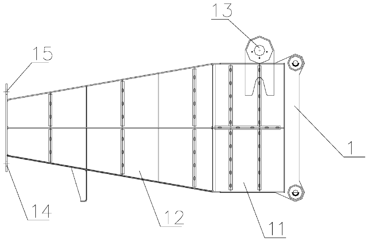
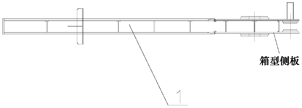
[0041] The combined scale beam and suspension beam device of the present embodiment is as Figure 1-4 As shown, the first beam suspension beam 1 comprising a flat box-shaped structure as a whole, the first beam suspension beam 1 includes a first equal-width section 11 and a first tapered section 12, and a first equal-width section 11 upper end is provided with a first A lifting lug 13, the tail end of the first scale beam 1 is provided with a counterweight connection hole 14, in addition, the end of the first tapered section 12 of the first scale beam 1 corresponds to the counterweight connection hole 14 and an auxiliary suspension is also provided. ear 15.

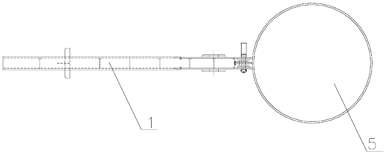
[0042] When the cross-section of the suspended object 5 is a circular or rectangular columnar frame structure, the end of the first equal-width section 11 of the first scale beam suspension beam 1 is matched with a suitable connecting mechanism such as a hoop or a bolt (specifically, it is only required that the two can b...

Embodiment 2

[0049] The combined scale beam and suspension beam device of the present embodiment is as Figure 5-10 As shown, in addition to the first beam beam 1, the beam beam device also includes a second beam beam 2 and a connecting beam 3. The second beam beam 2 is in a flat box-shaped structure as a whole, and the connecting beam 3 is in a plate shape. structure, and the second beam beam 2 includes a second equal width section 21 and a second tapered section 22, the upper end of the second equal width section 21 is provided with a second lug 23, the first beam beam 1 and the second beam crane The equal width sections of the beam 2 are respectively provided with two high and low hanging beam pin holes 6, and the two ends of the connecting beam 3 are respectively provided with two connecting beam pin holes 7, and the two sides of the connecting beam 3 are respectively inserted into the first scale beam hanging beam 1 and the Between the box-shaped side plates of the second scale beam s...


PUM


Abstract

The invention discloses a combined weighing rod lifting beam device, comprising two weighing rod lifting beams which separately have a flat box-shaped structure on the whole; each weighing rod liftingbeam comprises an equal width section and a gradual contraction section, wherein the upper end of each equal width section is provided with a lifting lug; the tail end of each weighing rod lifting beam is provided with a counterweight connection hole. The combined weighing rod lifting beam device solves the problem that a crane cannot lift from the upper part of a structure of an object to be lifted due to the insufficient lifting height; after the combined weighing rod lifting beam device is connected and fixed with the object to be lifted, the height required for lifting is lowered, and thelifting requirements are reduced. When the crane cannot lift from the upper part of the object to be lifted due to the insufficient lifting height, a main beam is formed by using a connecting beam torealize bolted fixation between the two weighing rod lifting beams, and the main beam and two side beams are connected and fixed with three apex structures of the triangular section of the object tobe lifted. After the main beam is disassembled, the two weighing rod lifting beams can be independently used for lifting a columnar structure with a circular or rectangular cross section.

Description

technical field [0001] The invention relates to a combined scale beam hanging beam device and a hoisting method thereof. Background technique [0002] In the field of hoisting, columnar structures are often designed as strong supporting structures because of their high structural strength and good structural stability. For example, the pile legs of the jack-up platform, and the support column between the upper and lower shells of the large offshore crane of the semi-submersible / bottomed platform. Among them, the pile leg structure is mainly triangular truss type, rectangular truss type and cylindrical type. Usually, the height of this type of structure is high, even exceeding the lifting height of the shipyard’s gantry crane. It needs to be hoisted with the help of a floating crane, which seriously restricts the integrity of the ship or platform before launching, resulting in a huge workload left behind on the wharf after launching, which affects the construction cycle and ...

Claims


Application Information

Patent Timeline
Patent Type & Authority Patents(China)
IPC IPC(8): B66C1/10B66C13/04
CPCB66C1/10B66C13/04
Inventor 何琎梁剑明沈士林郑勇周港
Owner 广州黄船海洋工程有限公司
Why Eureka
Try Eureka