Method and device for temperature compensation of MEMS sensor

A temperature compensation and sensor technology, applied in the field of temperature compensation, can solve the problems of increasing hardware cost of MEMS sensors, obstacles to miniaturization and cost reduction of equipment, and insufficiency of sensors, so as to reduce CPU burden, reduce waiting time, Effect of Consistency Guarantee

Inactive Publication Date: 2019-01-18
ALLWINNER TECH CO LTD
View PDF5 Cites 12 Cited by
  • Summary
  • Abstract
  • Description
  • Claims
  • Application Information

AI Technical Summary

Problems solved by technology

[0003] In the prior art, using an insulation box to insulate MEMS sensors will undoubtedly increase the investment in hardware costs and occupy a certain amount of physical space, which is an o...

Method used


Image

  • Method and device for temperature compensation of MEMS sensor
  • Method and device for temperature compensation of MEMS sensor
  • Method and device for temperature compensation of MEMS sensor

Examples


Embodiment 1

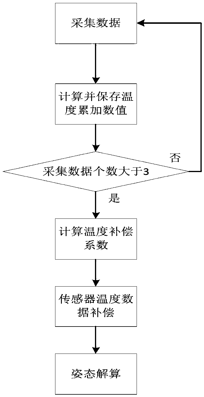
[0032] The flow process of the method of this embodiment is as follows figure 1 shown. Before describing the process, the theoretical basis of the method is introduced below.

[0033] (1) The specific implementation method of the fast temperature compensation algorithm.

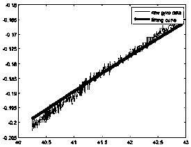
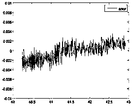
[0034] Assuming that the current sensor is in a static state, the ideal output should be the ideal initial value (this embodiment takes the gyroscope value, accelerometer, etc. as an example, and the ideal initial value is 0), but because of the influence of the ambient temperature change, its output It is not an ideal initial value (for example, a stationary gyroscope and accelerometer does not output a value of 0), but a biased value that has a certain relationship with temperature. This deviation is a static deviation, and compensating for this deviation is the main task of this embodiment.

[0035] After a lot of experiments, we found that the static bias output data of the sensor can be fitted into a ...

Embodiment 2

[0087] In this embodiment, on the basis of the above-mentioned first embodiment, the assurance of considering the applicable conditions of the fast temperature compensation algorithm in the first embodiment is added.

[0088] If the carrier is static during the entire use time, then the temperature compensation can always be in operation and the temperature compensation coefficient can be calculated in real time, but this is obviously an ideal state. In actual use, the entire MEMS sensor is required to move, and the accuracy of this method is greatly reduced during movement. Therefore, how to distinguish the movement state and continue to perform temperature compensation after the movement stops is the key to improving the feasibility and accuracy of the entire algorithm.

[0089] When in motion, the noise output by the sensor is very large, which is almost an order of magnitude difference compared with that at rest. Therefore, it is only necessary to calculate the variance of ...


PUM


Abstract

The invention relates to a method and device for temperature compensation of a MEMS sensor. The method comprises the steps of: collecting a plurality of sets of data of the sensor at different temperatures while the MEMS sensor is at a standstill, wherein each set of data comprises a sensor output value and a corresponding sensor temperature value at the moment; after the collection, firstly calculating an initial temperature compensation coefficient, then using an incremental method to continue the calculation of the temperature compensation coefficient; and calculating the static output compensation amount data of the sensor and the sensor output value after compensation according to the current temperature compensation coefficient. Because the software method is used to compensate by computer program, no additional hardware cost and additional physical space are added; with the incremental calculation method, the temperature compensation coefficient can be quickly calculated to reduce the waiting time; and the incremental calculation method is used to reduce the CPU burden and the memory footprint.

Description

technical field [0001] The invention relates to a method and device for temperature compensation of MEMS sensors, especially suitable for low-cost MEMS sensors, such as gyroscope values ​​and accelerometers used on moving carriers such as drones. Background technique [0002] Due to the process and design of the existing low-cost MEMS sensors, the output value will change due to the change of the external environment temperature, and the consistency of the data after each power-on cannot be guaranteed. In the application of low-cost MEMS sensors, there are few schemes to actively compensate the temperature of the sensor. Some companies have made a separate module for the part where the sensor is located, and have carried out constant temperature treatment on it. Now, most of the applications in the industry are limited to cooling the sensor part, or using heating resistors to achieve constant temperature in a certain temperature range. [0003] In the prior art, using an in...

Claims


Application Information

Patent Timeline
IPC IPC(8): G01C25/00G01P1/00
CPCG01C25/005G01P1/006
Inventor 刘兵吕元宙雷祥锋
Owner ALLWINNER TECH CO LTD
Why Eureka
Try Eureka