[0030] The technical solutions of the present invention will be described in further detail below with reference to the accompanying drawings and specific embodiments.
[0031] First, a brief description of the orientation words involved in the specific implementation manner is given: in this embodiment, the front-rear direction and the left-right direction are defined along the normal wearing state of the head-mounted virtual reality device.
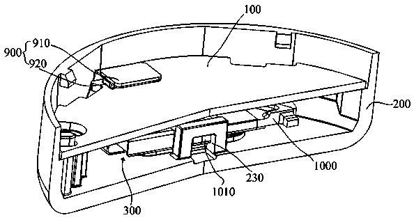
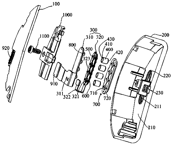
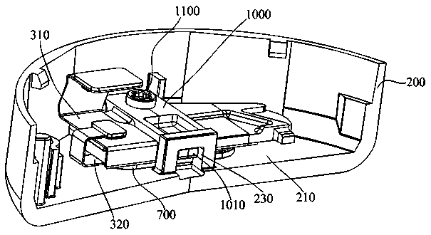
[0032] like Figure 1 to Figure 3 As shown, in this embodiment, a charging pin waterproof installation structure includes a mounting shell 200 , a main control board 100 , an FPC adapter board 300 and a charging pin 400 arranged in the mounting shell 200 , and the FPC adapter board 300 passes through the connector 900 It is connected with the main control board 100 to realize signal transmission. For the connector 900, a male connector 910 can be set on the FPC adapter board 300, and a female connector 920 can be set on the main control board 100. Through the male connector 910 and the The mating of the female connector 920 enables the connection; such as Figure 4 and Figure 5 As shown, the first end 410 (also referred to as its mounting end) of the charging pin 400 is fixed on one side of the FPC adapter board 300, and the second end 420 (also referred to as its charging connection end) of the charging pin 400 protrudes into the In the corresponding charging pin hole 211 provided on the side plate 210 of the mounting case 200; in this embodiment, the waterproof mounting structure for the charging pin further includes a humidity sensor 500, a temperature sensor 600, a heating device 800, and a heat-expandable and cold-shrinkable seal 700, which are all set on the FPC adapter board 300; such as figure 2 , Figure 4 and Figure 5 As shown, the humidity sensor 500 and the temperature sensor 600 are located around the charging pin 400 and are electrically connected to the main control board 100. Specifically, in this embodiment, they are connected to the main control board 100 through the contacts of the connector 900, so as to facilitate real-time detection The temperature and humidity at the position of the charging needle 400 are transmitted to the corresponding information processing module on the main control board 100 for processing; the heating device 800 adopts an electric heating coil in this embodiment, which is set corresponding to the charging needle 400 and communicated with the main control board. The board 100 is electrically connected, and specifically is connected to the main control board 100 through the contacts of the connector 900; Figure 4 and Figure 5 As shown, the sealing member 700 is arranged corresponding to the charging pin 400, and extends into the charging pin hole 211 and is sleeved on the charging pin 400, and the sealing member 700 has an interference fit with the charging pin hole 211 and the charging pin 400, so as to achieve sealing The component 700 seals the gap between the charging pinhole 211 and the charging pin 400 to prevent moisture and water vapor in the external environment from entering the interior of the mounting shell 200 through the gap between the charging pinhole 211 and the charging pin 400, that is, it plays a waterproof role.
[0033] The waterproof installation structure of the charging needle in this embodiment, by setting the temperature sensor 600 and the humidity sensor 500 around the charging needle 400 to detect the temperature and humidity at the position of the charging needle 400 in real time, realize the real-time detection and control of the waterproof position of the charging needle 400 of the product, The waterproof stability and reliability are greatly improved. When the temperature detected by the temperature sensor 600 is low, the heating device 800 is controlled by the main control board 100 to be heated, so that the sealing member 700 is heated and expanded, thereby strengthening the sealing member 700 and the charging pinhole 211 and The interference amount and squeezing force of the interference fit between the charging pins 400 can improve the sealing effect of the seal 700 on the charging pin hole 211 and the gap between the charging pins 400 , and improve the waterproof effect of the charging pins 400 .
[0034] Further, as figure 2 , Figure 4 , Figure 5and Figure 7 As shown, the sealing member 700 includes a plate-shaped part 720 and a cylindrical part 710 that are integrally formed. The plate-shaped part 720 covers the side where the charging needle 400 is located; the cylindrical part 710 is on one side of the plate-shaped part 720; the cylindrical part 710 It extends into the charging pinhole 211 and is sleeved on the charging pin 400 , and the cylindrical portion 710 has an interference fit with the charging pinhole 211 and the charging pin 400 . In this way, the sealing member 700 is divided into two parts. The plate-shaped part 720 covers the side of the FPC adapter board 300 where the charging pin 400 is located; Comprehensively achieve sealing and improve sealing and waterproofing effect.
[0035] In order to facilitate the setting of various components, such as Figure 1 to Figure 7 As shown, the FPC adapter board 300 includes a charging pin FPC board 310 and a sensor FPC board 320. Specifically, the charging pin FPC board 310 is provided with a pad 311, the sensor FPC board 320 is provided with a solder joint 324, and the charging pin FPC board is provided with 310 and the sensor FPC board 320 are welded and connected to the solder joints 324 through the pads 311 to form an integrated FPC adapter board 300; the charging pin FPC board 310 and the main control board 100 are connected through the connector 900 to realize the entire FPC adapter board 300 Connection with the main control board 100; specifically, the first end 410 of the charging pin 400 is fixed on one side of the charging pin FPC board 310, and the heating device 800 is arranged on the charging pin FPC board 310, such as figure 2 , Figure 4 , Figure 5 and Figure 7 From the perspective shown, the charging pin 400 and the heating device 800 are both disposed on the bottom side of the charging pin FPC board 310; the sensor FPC board 320 is located between the charging pin FPC board 310 and the side plate 210 of the mounting shell 200 where the charging pin hole 211 is located. The sealing member 700 is fixed on the sensor FPC board 320. The sensor FPC board 320 is provided with a through hole 321 corresponding to the charging pin 400 for the charging pin 400 and the cylindrical portion 710 to pass through. The humidity sensor 500 and the temperature sensor 600 are both provided. It is fixed on the sensor FPC board 320 .
[0036] Since the FPC board itself is soft, in order to stably support the components on the charging pin FPC board 310 and the sensor FPC board 320 without shaking, a plurality of stainless steel reinforcing plates 330 are arranged on the charging pin FPC board 310 and the sensor FPC board 320, which can The stainless steel reinforcing plate 330 is connected to the charging pin FPC board 310 and the sensor FPC board 320 by welding to improve the strength of the charging pin FPC board 310 and the sensor FPC board 320 and avoid deformation.
[0037] In order to facilitate the connection between the sensor FPC board 320 and the charging pin FPC board 310, such as Figure 7 As shown, the sensor FPC board 320 includes a connecting portion 322 connected to the charging pin FPC board 310 and a mounting portion 323 for setting the humidity sensor 500 and the temperature sensor 600. The mounting portion 323 has an outer side facing the side where the charging pin hole 211 is located and The inner side facing away from the side where the charging pinhole 211 is located, the humidity sensor 500 is located on the inner side of the mounting portion 323, and the temperature sensor 600 is located on the outer side of the mounting portion 323, that is, the temperature sensor 600 is located closer to the mounting portion than the humidity sensor 500. The outer side of the shell 200, so that the temperature sensor 600 detects the temperature on the outer side to preliminarily determine whether there is a risk of water ingress. If the temperature is lower than the set temperature, there is a risk of water ingress, and then the humidity sensor 500 on the inner side detects the internal Humidity, it has been finally confirmed whether water has entered.
[0038] The heat-expandable and cold-shrinkable sealing member 700 in this embodiment is made of a soft rubber material, such as silica gel, which is fixed on the sensor FPC board 320 by insert molding, and wraps the mounting portion 323 , the humidity sensor 500 and the temperature The sensors 600 are embedded in the sealing member 700, and the probe parts of the humidity sensor 500 and the temperature sensor 600 are both exposed to the sealing member 700, such as Figure 7 shown. The sealing member 700 is fixed on the sensor FPC board 320 by means of insert molding, which is convenient to form, especially convenient for integral molding with the sensor FPC board 320 with complex shape, and the humidity sensor 500 and the temperature sensor 600 are embedded in the sealing member 700, and no need In addition, the fixed structure of the sensor is provided, which reduces the complexity of the structure and the processing cost. Of course, the sealing member 700 can also be made of other materials, such as plastic parts, as long as the sealing member 700 has thermal expansion and contraction efficiency.
[0039] In order to improve the heating efficiency, such as Figure 5 and Image 6 As shown, the charging needle 400 has an inner cavity 430, and the heating device 800 is located in the inner cavity 430 of the charging needle 400, so that the heating device 800 is closest to the charging needle 400, thereby heating the charging needle 400 most directly and fastest, and improving the heating efficiency. Moreover, the heating device 800 is located in the inner cavity 430 of the charging pin 400, which saves other space of the charging pin FPC board 310, simplifies its external structure, and facilitates the arrangement of other components.
[0040] Since the number of the charging pins 400 is generally multiple, correspondingly, the through holes 321 and the charging pin holes 211 are the same as the number of the charging pins 400 , and a plurality of humidity sensors 500 and temperature sensors are arranged around each through hole 321 600, so as to conduct a comprehensive waterproof test at the position of each charging pin 400.
[0041] The side plate 210 where the charging pinhole 211 is located is provided with a raised annular rib 220, such as figure 2 , Figure 4 and Figure 5 As shown, the charging pinhole 211 is located inside the annular rib 220, and the outer peripheral edge of the sealing member 700 is in interference fit with the annular rib 220 and interfered with assembly, thereby facilitating the waterproof safety of the peripheral ring and reducing other possible waterproof abnormality or method failure. factors, so that when abnormal waterproofing or waterproofing failure occurs, it can be confirmed that it is caused by poor sealing between the charging pin hole 211 and the charging pin 400 .
[0042] Further, in order to ensure the reliability of the interference fit between the sealing member 700 and the annular rib 220 and increase the amount of interference and the pressing force between the two, the waterproof installation structure of the charging needle in this embodiment also includes a charging needle that is fixed inside the installation shell 200 . The pressure plate 1000 is located above the FPC adapter plate 300 and has pressure on the seal 700. Specifically, as Figure 3 to Figure 5 As shown, one end of the pressing plate 1000 is fixed to the mounting shell 200 by screws 1100, the other end of the pressing plate 1000 is provided with a buckle 1010, and the mounting shell 200 is correspondingly provided with a locking hole 230, and the locking buckle 1010 is engaged with the locking hole 230, thereby The waterproof detection module is pressed on the installation shell 200. Since the FPC adapter plate 300 is soft, in order to further ensure its stability, the FPC adapter plate 300 is also pasted and fixed on the pressure plate 1000 by double-sided tape. The control board 100 is fixed to the installation shell 200 by positioning one end and fixing one end with screws.
[0043] This embodiment also proposes a charging pin waterproof detection method. Based on the charging pin waterproof installation structure described in this embodiment, the specific steps are as follows, and the specific process is as follows Figure 8 shown:
[0044] 1) The temperature sensor detects the temperature at the position of the charging needle, and the detected temperature signal is transmitted to the main control board. The corresponding information processing module on the main control board receives the temperature signal and calculates the temperature value T detected by the temperature sensor and the set temperature value. T 0 The difference △T, △T= T-T 0;
[0045] 2) When △T < 0, that is, the temperature at the position of the charging pin is lower than the set temperature value, there may be a problem of waterproof failure. At this time, the main control board controls the heating device to start working, and the seal is heated and expanded. Specifically, through the heating device The work makes the charging needle heat up, and the heat conduction of the charging needle is conducted to the sealing member. According to the effect of thermal expansion and cold contraction, the sealing member is heated and expands to increase the amount of interference and extrusion force between the charging needle and the charging needle hole, thereby Block the water vapor or water droplets outside the mounting case; of course, if △T≥0, you can return to step 1 to continue the temperature detection at the position of the charging needle;
[0046] 3) When the heating device works to △T=0, that is, the temperature at the position of the charging pin rises to equal to the set temperature value, the main control board controls the heating device to stop working, and controls the humidity sensor to start working to detect the temperature at the position of the charging pin. humidity, and transmit the detected humidity signal to the main control board. The corresponding information processing module on the main control board receives the humidity signal and calculates the humidity value H detected by the humidity sensor and the set humidity value H 0 The difference △H, △H = H-H 0 , to confirm whether the heating by the heating device at the position of the charging pin 400 effectively eliminates the risk of waterproof failure;
[0047] 4) If △H<0, that is, the humidity value H at the position of the charging needle is less than the set humidity value H 0 , confirm that the risk of waterproof failure has been eliminated, and the waterproof is good; if △H≥0, that is, the humidity value H at the position of the charging pin is large, confirm the waterproof failure, and confirm whether there are water droplets or water droplets in the installation shell to avoid short circuit of the internal circuit board. .
[0048] Further, in step 4), if it is confirmed that the waterproof failure has occurred, the waterproof failure treatment needs to be carried out. Since the gap between the charging pin and the charging pin hole is the main reason for the waterproof failure, the side where the charging pin is located (also The main control board controls the heating device to start to work and heat to evaporate the water. Since the water volatilizes and flows upward when it evaporates into a gaseous state, the side where the charging needle is located is facing up, so that when the steam flows upward, the charging needle and the The gap between the charging pinholes flows out; at the same time, the humidity sensor detects the humidity at the location of the charging pin in real time. When the detected humidity value H and the set humidity value H 0 When the difference △H<0, that is, the humidity value H at the position of the charging needle is less than the set humidity value H 0 , the main control board controls the heating device to stop heating, and the waterproof failure treatment is completed.
[0049] The heating temperature of the heating device during the waterproof failure treatment should be higher than the heating temperature of the heating device in step 2) of the test method of this embodiment. This is because the purpose of heating the heating device during the waterproof failure treatment is to evaporate the internal moisture, and the heating temperature is about 40°C, and the purpose of heating the heating device in step 2) is to heat the seal to expand, so it needs to be heated slowly, and the heating temperature is about 25°C. Of course, the waterproof failure treatment can also be professionally handled by professional departments, and the specific treatment can be carried out according to the specific situation.
[0050] The waterproof installation structure of the charging needle in this embodiment can be widely used in wearable electronic products, such as smart bracelets or smart wristbands, or other electronic products. This embodiment also proposes a wrist-worn device with a charging pin waterproof installation structure. The specific structure of the charging pin waterproof installation structure can be found in the embodiments of the charging pin waterproof installation structure of the present invention and its appendices. Figure 1 to Figure 8 description, which will not be repeated here.
[0051] The above embodiments are only used to illustrate the technical solutions of the present invention, but not to limit them; although the present invention has been described in detail with reference to the foregoing embodiments, those of ordinary skill in the art can still The recorded technical solutions are modified, or some technical features thereof are equivalently replaced; and these modifications or replacements do not make the essence of the corresponding technical solutions deviate from the spirit and scope of the technical solutions claimed in the present invention.