Condition control device and condition control method for spatial lateral restraint loading of test component

A technology of lateral restraint and loading device, which is applied in the field of experimental mechanics, can solve problems such as difficult to accurately reproduce boundary conditions, do not consider loading system errors, and low accuracy and reliability of test results, so as to improve accuracy and reduce adverse effects Effect

Active Publication Date: 2019-01-18
CHINA STATE CONSTRUCTION ENGINEERING CORPORATION
View PDF9 Cites 0 Cited by
  • Summary
  • Abstract
  • Description
  • Claims
  • Application Information

AI Technical Summary

Problems solved by technology

[0004] The present invention proposes a condition control device and control method for space lateral constraint loading of test components, which solves the problem that the boundary conditions of component constraints in traditional tests are difficult to reproduce accurately, the error of the loading system is not considered in the test, and the accuracy and reliability of the test results are solved. Low reliability technical issues

Method used


Image

  • Condition control device and condition control method for spatial lateral restraint loading of test component
  • Condition control device and condition control method for spatial lateral restraint loading of test component
  • Condition control device and condition control method for spatial lateral restraint loading of test component

Examples


Embodiment Construction

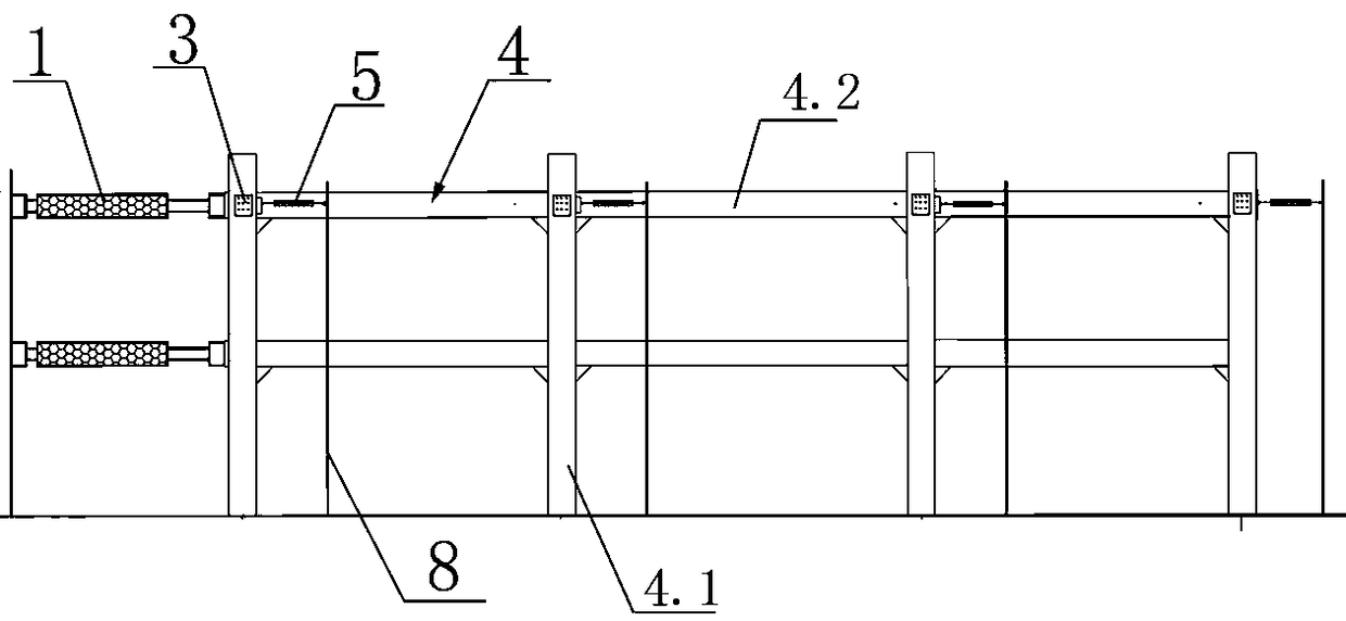
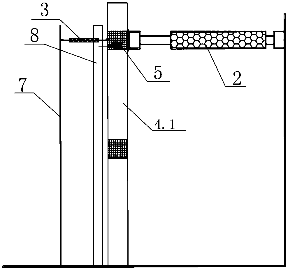
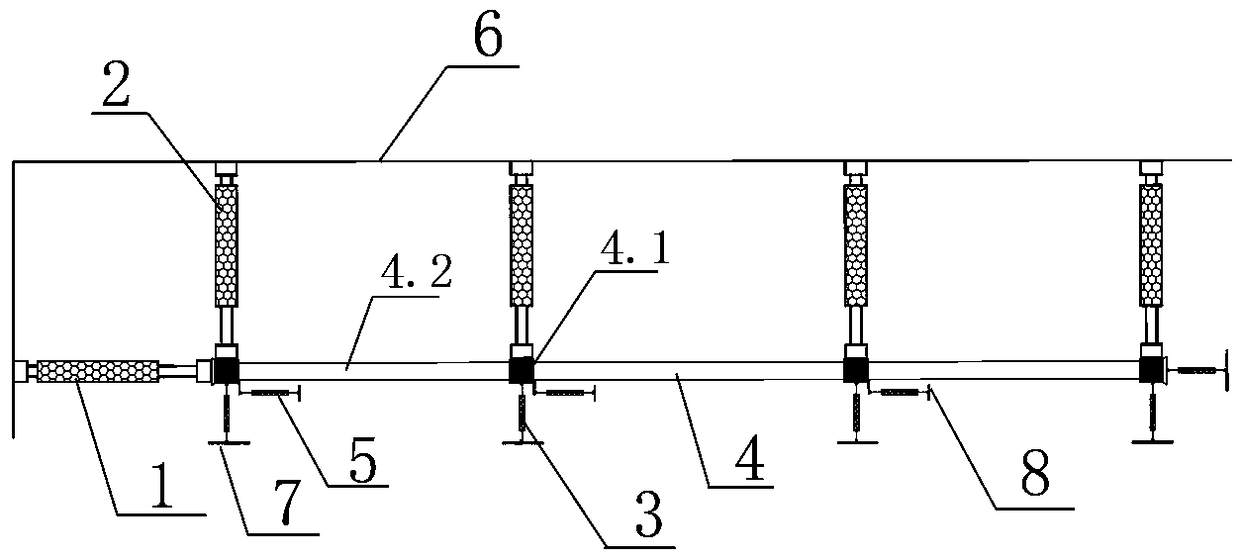
[0035] Such as Figure 1-3As shown, the condition control device for the space lateral restraint loading of the test member includes a loading device 1 and a restraint device 2; the loading device 1 has at least one group, which is arranged on the longitudinal side of the test member 4; wherein, each group The loading devices 1 are vertically arranged in parallel at intervals, and each loading device 1 is set corresponding to the node position of the test member 4; the free end of the loading device 1 is horizontally connected to the test member 4 to apply the main loading direction to the nodes Load; the restraint device 2 has one group, and the free end of the restraint device 2 is horizontally connected to the test member 4 on one lateral side of the test member 4 to constrain the lateral displacement of the node; At each node, on the opposite side of the corresponding constraint device 2, a first displacement measurement device 3 is arranged; the first displacement measure...


PUM


Abstract

The invention discloses a condition control device and a condition control method for spatial lateral restraint loading of a test component, wherein the condition control device comprises loading devices and restraining devices, wherein there is at least one set of loading devices disposed on a longitudinal side of the test component; each loading device is correspondingly set with the node position of the test component; there is one set of restraining devices disposed on a lateral side of the test component for constraining the lateral displacement of the nodes; first displacement measuringdevices are arranged at each node of the test component and on the opposite side of the corresponding restraining device; a set of second displacement measuring devices are arranged on the opposite side of each set of loading devices on the test component along the lateral interval; and the second displacement measuring devices are used for measuring the actual main loading direction displacementof the corresponding nodes on the test member. The condition control device and condition control method for spatial lateral restraint loading of a test component solve the technical problem that theboundary condition of the component constraint in the traditional experiment is difficult to accurately reproduce, the loading system error is not considered in the test, and the precision and credibility of the test result are low.

Description

technical field [0001] The invention relates to the field of experimental mechanics, and specifically relates to a feedback control device and a control method for a civil engineering structure test component space lateral restraint loading. Background technique [0002] Due to the huge size of building structures, it is difficult to carry out full-scale structural tests due to the constraints of economy and test environment. Generally, the key parts of the structure or the parts with complex and concentrated forces are selected for research. In this way, selecting components in the structure for mechanical performance research inevitably needs to restore the real force state of the component boundary, that is, the reproduction of component boundary conditions. [0003] At present, only the sensitive degrees of freedom among component boundary degrees of freedom are usually considered in the process of reproducing boundary conditions, that is, some sensitive rotation angles ...

Claims


Application Information

Patent Timeline
Patent Type & Authority Applications(China)
IPC IPC(8): G01M13/00
CPCG01M13/00G01N2203/0682
Inventor 田振史鹏飞罗叶孙建运王贞王照然许国山吴斌杨格郭海山刘康
Owner CHINA STATE CONSTRUCTION ENGINEERING CORPORATION
Why Eureka
Try Eureka