
Real-time measuring device and system for runoff sediment content

A technology for real-time measurement of sediment content, applied in measurement devices, suspension and porous material analysis, particle suspension analysis, etc., can solve the problems of large measurement error, difficult to measure accurately, complicated operation, etc. The effect of measuring costs

Pending Publication Date: 2019-01-18
WUHAN NEWFIBER OPTOELECTRONICS TECH +1
View PDF0 Cites 4 Cited by
  • Summary
  • Abstract
  • Description
  • Claims
  • Application Information

AI Technical Summary

Problems solved by technology

[0002] At present, there are two methods used to measure the runoff sediment content. One is the direct measurement method, such as the drying method, also known as the weighing method. Determine the sand content in the mud water, but because the drying method needs to dry the sample to be tested, and the drying temperature is generally 105°, heating takes about 11 hours, high temperature and long-term heating will cause the organic matter in the soil to be carbonized, and The measured sediment concentration is relatively small, and the requirements for drying temperature and heating time also make the entire measurement process time-consuming and laborious. When using the drying method to measure the sediment concentration on-site, it will cause a large error in the measured sediment concentration, and the operation Complicated, low efficiency, unable to achieve online continuous monitoring; another method is indirect measurement method, such as capacitance method, laser method, Y-ray method, etc. , temperature, etc., the measurement error is relatively large, especially when the sediment concentration is large or small, it is difficult to achieve accurate measurement

Method used


Image

  • Real-time measuring device and system for runoff sediment content
  • Real-time measuring device and system for runoff sediment content
  • Real-time measuring device and system for runoff sediment content

Examples


Embodiment Construction

[0046] The following will clearly and completely describe the technical solutions in the embodiments of the present invention with reference to the accompanying drawings in the embodiments of the present invention. Obviously, the described embodiments are only part of the embodiments of the present invention, not all of them. Based on the embodiments of the present invention, all other embodiments obtained by persons of ordinary skill in the art without creative efforts fall within the protection scope of the present invention.

[0047] It should be noted that if there are directional indications involved in the embodiment of the present invention, the directional indications are only used to explain the relative positional relationship, movement conditions, etc. between the components in a specific posture. If the specific posture changes , then the directional indication changes accordingly.

[0048] In addition, if there are descriptions involving "first", "second" and so o...


PUM


Abstract

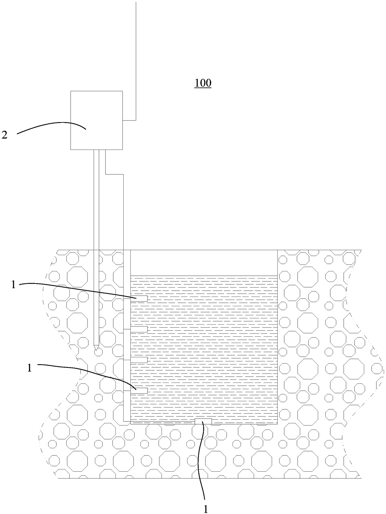
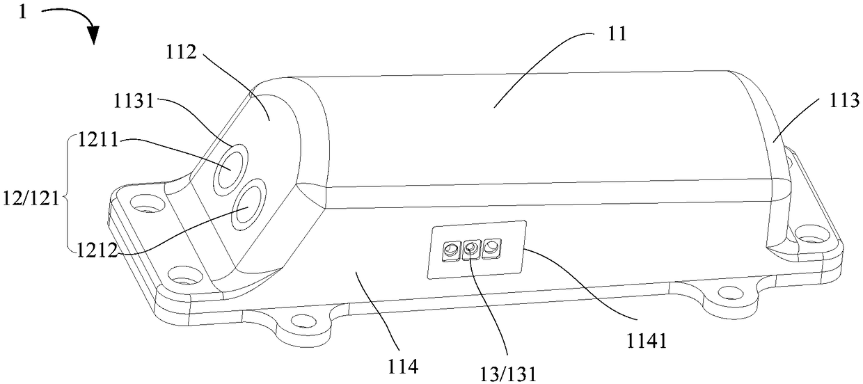
The invention discloses a real-time measuring device and system for the runoff sediment content. The real-time measuring device for the runoff sediment content comprises a plurality of integrated detecting heads and a collecting box. The multiple integrated detecting heads are used for being placed at different liquid levels of the same section of runoff correspondingly to measure the runoff flowing speed and the sediment concentrations of the different liquid levels of the same section. The collecting box is provided with a collecting analyzing assembly which is electrically connected to themultiple integrated detecting heads. The multiple integrated detecting heads are placed at the different liquid levels of the same section of the runoff, and all the integrated detecting heads can measure the sediment concentrations of the liquid levels. The sediment concentration of the whole runoff can be obtained through the sediment concentrations of the multiple liquid levels. The sediment discharge per unit time can be obtained through the runoff flowing speed, the sediment concentration, the liquid levels and the runoff width. The sediment concentration and the sediment discharge reflect the sediment content of the runoff, that is, the runoff sediment content is measured, measuring work is reduced greatly, and the measuring cost is saved.

Description

technical field [0001] The invention relates to the technical field of river sediment measurement, in particular to a runoff sediment content measurement device and a real-time measurement system. Background technique [0002] At present, there are two methods used to measure the runoff sediment content. One is the direct measurement method, such as the drying method, also known as the weighing method. Determine the sand content in the mud water, but because the drying method needs to dry the sample to be tested, and the drying temperature is generally 105°, heating takes about 11 hours, high temperature and long-term heating will cause the organic matter in the soil to be carbonized, and The measured sediment concentration is relatively small, and the requirements for drying temperature and heating time also make the entire measurement process time-consuming and laborious. When using the drying method to measure the sediment concentration on-site, it will cause a large erro...

Claims


Application Information

Patent Timeline
Patent Type & Authority Applications(China)
IPC IPC(8): G01N15/06
CPCG01N15/06G01N15/075
Inventor 游政园张春萍刘伟刚陈翔李立青张继华刘方义潘凌徐锦锋武治国
Owner WUHAN NEWFIBER OPTOELECTRONICS TECH
Learn More