
Card skimmer detection

A technology of stolen swipe and card reader, applied in the field of card swipe detection, can solve problems such as problems in the industry

Active Publication Date: 2021-09-21
NCR CORP
View PDF5 Cites 0 Cited by
  • Summary
  • Abstract
  • Description
  • Claims
  • Application Information

AI Technical Summary

Problems solved by technology

Meanwhile, thieves have developed skimmers that steal card information from touchpoints embedded in chips, and banks are currently failing to produce any reliable skimmer detection and prevention hardware and software security.
[0004] As a result, skimmers pose a significant challenge in the card industry and will continue to be problematic for the industry in the foreseeable future

Method used


Image

  • Card skimmer detection
  • Card skimmer detection
  • Card skimmer detection

Examples


Embodiment Construction

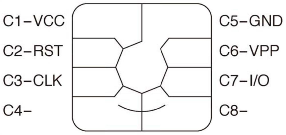
[0034] Figure 1A is a diagram illustrating contact points on a chip typically embedded in a card according to an example embodiment.

[0035] When a card with an embedded chip is inserted into a card reader, the segmented areas of the chip provide various chip contact points with the card reader. C1 (called VCC) provides power to the chip from the card when it makes contact inside the card reader. C2 provides a contact within the reader for the reset signal. C3 provides a contact within the reader for the clock signal. C4 is reserved as a touchpoint for future expansion. C5 provides a contact point within the reader for grounding. C6 provides a contact point within the reader for a variable supply voltage (called VPP). C7 provides a contact point within the reader for input / output (I / O) of information supplied to and by the card when the card is inserted into the reader. C8 is reserved as a second touch point for future expansion and is used like C4.

[0036] Skimmers a...


PUM


Abstract

A brush fraud detection device (402) is selectively interfaced to part of a chip card reader (401) integrated in a terminal. The swiping detection means is configured to detect when a swiping device is inserted into the chip card reader during a card transaction at the terminal, and to take automatic action in response thereto.

Description

technical field [0001] This application relates to card skimmer detection. Background technique [0002] The industry lacks any technology for detecting card "swipes". Skimmer device steals information from card chip and pays from Euro and (EMV) card theft of a personal identification number (PIN). Brush skimmers are starting to become the device of choice for thieves in the industry because there are various mechanisms for detecting skimmers, but none available for detecting skimmers. Skimmers read the card's magnetic stripe, while skimmers steal data from predefined touch points on the card, such as specific locations on the card's embedded chip. [0003] Banks have been concerned with skimmer detection and during the process have changed consumer cards to cards with embedded chips, which are believed to be more secure than cards without embedded chips. Meanwhile, thieves have developed skimmers that steal card information from touchpoints embedded in chips, and ban...

Claims


Application Information

Patent Timeline
Patent Type & Authority Patents(China)
IPC IPC(8): G07F19/00G06K7/00
CPCG01R31/2832G06K7/0013G06K7/0091G06K19/073G06Q20/341G06Q20/382G06Q20/4016G06Q20/4097G07F7/1016G08B13/00
Inventor 维斯顿·李·赫克
Owner NCR CORP
Learn More