Zero-position calibration system and method for permanent magnet synchronous motor

A permanent magnet synchronous motor, zero calibration technology, applied in the direction of measuring electrical variables, measuring devices, instruments, etc., can solve the problems of complex and time-consuming operation, time-consuming operation process, etc., achieve short calibration time, simple operation, and save the bench The effect of the installation process

Active Publication Date: 2019-01-18
HEFEI JUYI POWER SYST CO LTD
View PDF7 Cites 8 Cited by
  • Summary
  • Abstract
  • Description
  • Claims
  • Application Information

AI Technical Summary

Problems solved by technology

[0003] Currently, to obtain the zero position of the resolver through bench calibration, the motor and the corresponding motor controller need to be installed on the test bench, and then the tester operates the bench and related control host computer, and the zero position of the resolver needs to be continuously debugged. Acquisition, operation is complicated and time-consuming, and the accuracy needs to be further verified; the method of using the dynamometer to drag the motor to collect the back EMF also needs to install the motor on the side of the dynamometer, and use the dynamometer to drag the motor to a certain speed to collect the back EMF , using the counter electromotive force zero-crossing angle to obtain by comparing the read angle of the resolver. On the one hand, this method relies on the dynamometer to drag, and on the other hand, it needs a special device or circuit to realize it. The entire operation process is also time-consuming.

Method used


Image

  • Zero-position calibration system and method for permanent magnet synchronous motor
  • Zero-position calibration system and method for permanent magnet synchronous motor

Examples


Embodiment Construction

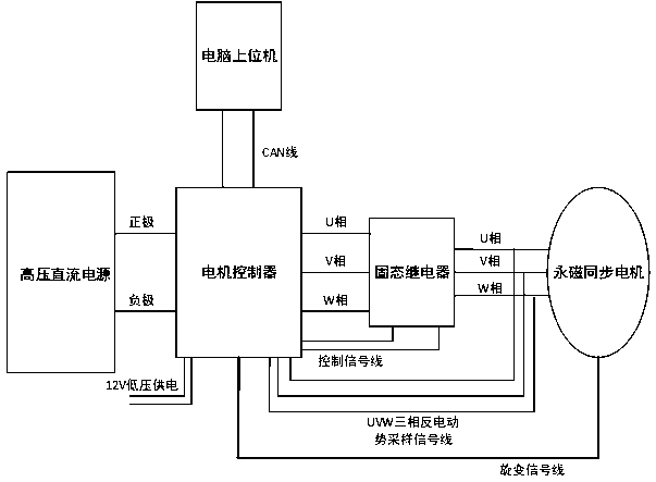
[0030] Such as figure 1 As shown, the permanent magnet synchronous motor resolver zero calibration system of the present invention includes a high-voltage DC power supply, a motor controller, a relay, and a permanent magnet synchronous motor connected in sequence. The control board of the motor controller is also designed with three phases Electromotive force sampling circuit, voltage comparison circuit, resolver value latch mode selection circuit and relay control circuit; the input of the motor controller is respectively connected to the positive and negative poles of the high-voltage DC power supply, and a 12V low-voltage power supply is provided, and the three-phase output of the motor controller is connected to the The three-phase input of the relay is connected, and the three-phase output of the relay is connected with the three-phase input line of the motor.

[0031] The three-phase electromotive force sampling circuit is connected to the three-phase input line of the p...


PUM


Abstract

The invention discloses a zero-position calibration system and method for a permanent magnet synchronous motor. The system comprises a high-voltage DC power supply, a motor controller, a relay and a permanent magnet synchronous motor which are connected in sequence, wherein a control board of the motor controller is also designed with a three-phase back electromotive force sampling circuit, a voltage comparison circuit, a rotation value latching mode selection circuit and a relay control circuit respectively; and the motor controller is also connected with an upper computer through a CAN line.According to the scheme, a control board circuit and a control program of the motor controller are added and modified, thereby realizing one-key calibration of the rotational zero position of the motor without additional circuit and dynamometer dragging, and omitting a complicated bench mounting process. The zero-position calibration system and method are easy to operate, and short in calibrationtime. According to the scheme, a rotational zero position is calculated by means of forward and reverse rotation and filter averaging under the same accelerating torque and limited rotational speed,so that the algorithm is more reasonable and more accurate, and the problem of circuit delay does not need to be considered.

Description

technical field [0001] The invention relates to a permanent magnet synchronous motor, in particular to a permanent magnet synchronous motor resolver zero calibration system and a calibration method. Background technique [0002] Permanent magnet synchronous motors have been widely used in electric vehicle drive systems, and their speed detection and control are inseparable from the motor rotor position. At present, the motor rotor position detection is usually realized by a resolver and a corresponding decoding circuit. The detection accuracy of the zero position of the motor resolver will directly affect the performance, efficiency and other indicators of the permanent magnet synchronous motor. Existing methods for detecting the zero position of the resolver usually use bench calibration or use a dynamometer to drive a motor to collect back electromotive force. [0003] Currently, to obtain the zero position of the resolver through bench calibration, the motor and the corr...

Claims


Application Information

Patent Timeline
Patent Type & Authority Applications(China)
IPC IPC(8): G01R35/00
CPCG01R35/005
Inventor 刘蕾方质彬班建安张茨
Owner HEFEI JUYI POWER SYST CO LTD
Why Eureka
Try Eureka