Device and method for calibrating working positions of polishing head and loading and unloading table

A technology of working position and polishing head, which is applied in the manufacturing of electrical components, circuits, semiconductor/solid-state devices, etc., can solve the problems of large amount of sensor detection data, unrealized loading and unloading table centering, and no mention of centering loading and unloading table, etc. Achieve the effect of high calibration efficiency, excellent data processing method, and low installation location requirements

Pending Publication Date: 2022-06-28
HANGZHOU ZHONGGUI ELECTRONICS TECH CO LTD
View PDF1 Cites 1 Cited by
  • Summary
  • Abstract
  • Description
  • Claims
  • Application Information

AI Technical Summary

Problems solved by technology

[0004] Chinese patent CN110411344B discloses "A Calibration Method, Calibration Device, Calibration System and Electronics", which needs to use four distance values ​​to complete the centering, and the four distance values ​​​​only complete the loading and unloading of the polishing head by rotating the polishing head Table centering, loading and unloading table is fixed, no mention of centering loading and unloading table
The device is relatively cumbersome, the centering efficiency is low, and the centering of the loading and unloading table has not been realized
Moreover, the four sensors detect a large amount of data, and at the same time there are complex calculations, which take a long time to align

Method used


Image

  • Device and method for calibrating working positions of polishing head and loading and unloading table
  • Device and method for calibrating working positions of polishing head and loading and unloading table
  • Device and method for calibrating working positions of polishing head and loading and unloading table

Examples


Embodiment 1

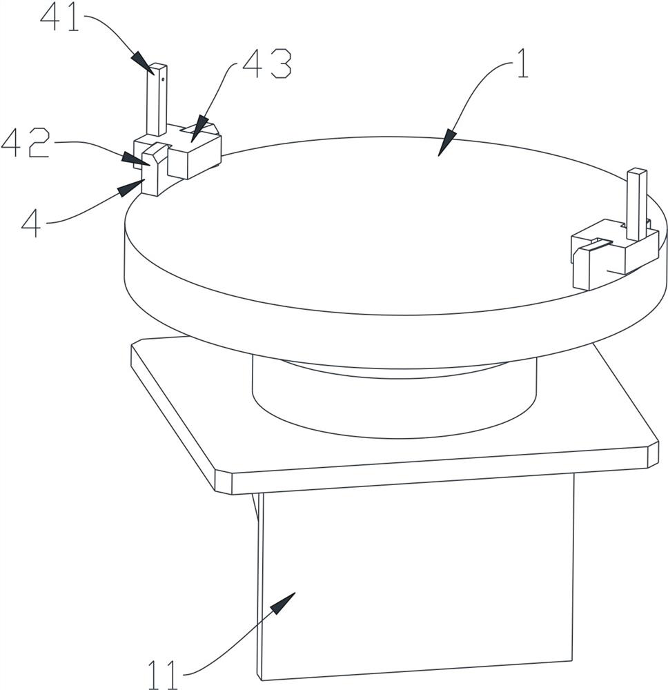
[0092] like Figure 5 , Image 6 As shown, the number of sensors 41 is two at this time, which are not only arranged along the radial direction of the loading and unloading platform 1 , but also along the extending direction of the linear track 2 .

[0093] A method for calibrating the working positions of a polishing head and a loading and unloading table, comprising the following steps:

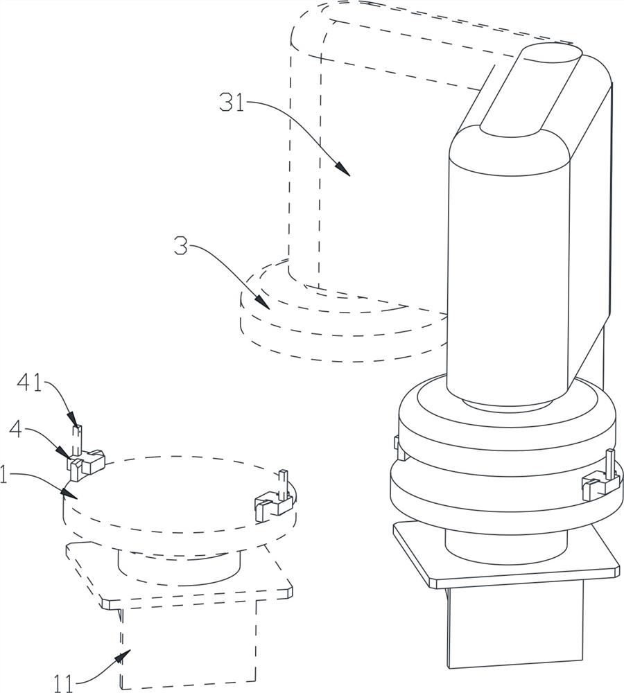
[0094] Install the sensor assembly 4 to the loading and unloading table 1, manually move the loading and unloading table 1 and the polishing head 3 close to each other, and calibrate the reading of the sensor 41;

[0095] Determine the rotation trajectory 5 of the polishing head 3, and use the angle range where the sensors 41 at both ends of the loading and unloading table 1 can display the reading as the swing range of the polishing head 3, and record the start position and end position, and define two sensors 41 and polishing. The readings of the edge of head 3 are L1 and L2 respectivel...

Embodiment 2

[0102] like Figure 7 , Figure 8 As shown, at this time, the number of sensors 41 is two, which are not only arranged along the radial direction of the loading and unloading platform 1 , but also along the direction perpendicular to the linear track 2 .

[0103] In this embodiment, the method for calibrating the working positions of the polishing head and the loading and unloading table is the same as that in the first embodiment, and will not be repeated.

Embodiment 3

[0105] like Figure 9 , Figure 10 As shown, the number of sensors 41 is two at this time, and they are only arranged along the radial direction of the loading and unloading platform 1 , not along the direction perpendicular to the linear track 2 , nor along the extension direction of the linear track 2 .

[0106] At this time, the working positions of the polishing head and the loading and unloading table can be calibrated with the directions in the first embodiment, and the following methods can also be used for calibration.

[0107] A method for calibrating the working positions of a polishing head and a loading and unloading table, comprising the following steps:

[0108] Install the sensor assembly 4 to the loading and unloading table 1, manually move the loading and unloading table 1 and the polishing head 3 close to each other, and calibrate the reading of the sensor 41;

[0109] Determine the rotation trajectory 5 of the polishing head 3, and use the angle range wher...


PUM


Abstract

The invention discloses a device for calibrating the working positions of a polishing head and a loading and unloading table, which comprises a loading and unloading table, a polishing head and a polishing head, the polishing head can rotate in the circumferential direction, and the rotating track and the linear track of the polishing head have at least one intersection point; the sensor assembly is used for monitoring the change of the distance between the outer edge of the polishing head and a sensor, and comprises the sensor which at least can measure the distance at the two radial ends of the loading and unloading platform; the judging unit is used for outputting the minimum linear distance, monitored by the sensor assembly, between the outer edge of the polishing head and the sensor so as to judge whether the central axes of the polishing head and the loading and unloading table coincide or not. The invention further discloses a method for calibrating the working positions of the polishing head and the loading and unloading table. The calibration efficiency is high, and the requirement for the installation position of the sensor is low; the detection error is small.

Description

technical field [0001] The invention belongs to the technical field of semiconductor integrated circuit chip manufacturing, and in particular relates to a device and method for calibrating the working positions of a polishing head and a loading and unloading table. Background technique [0002] Chemical Mechanical Planarization (Chemical Mechanical Planarization, CMP for short) equipment generally includes a semiconductor equipment front-end module (EFEM), a cleaning unit, and a polishing unit. EFEM mainly includes a cassette for storing wafers, a wafer transfer robot and an air purification system, etc.; the cleaning unit mainly includes various megasonic cleaning components, rolling brush cleaning components, drying components and devices for transferring wafers between components, etc. ; The polishing unit usually includes parts such as a workbench, a polishing disc, a polishing head, a polishing arm, a dresser, and a polishing liquid arm, and each part is arranged on the...

Claims


Application Information

Patent Timeline
Patent Type & Authority Applications(China)
IPC IPC(8): H01L21/67H01L21/68H01L21/306
CPCH01L21/67092H01L21/68H01L21/30625
Inventor 徐枭宇周杲翔蔡宁远
Owner HANGZHOU ZHONGGUI ELECTRONICS TECH CO LTD
Why Eureka
Try Eureka