Display panel and display device

A display panel and substrate substrate technology, applied in the direction of instruments, semiconductor devices, optics, etc., can solve problems affecting display quality, affecting pixel density, high resolution, etc., to achieve rich display screen details, avoid coupling effects, and facilitate narrow borders effect

Active Publication Date: 2021-09-28
SHANGHAI TIANMA MICRO ELECTRONICS CO LTD
View PDF6 Cites 0 Cited by
  • Summary
  • Abstract
  • Description
  • Claims
  • Application Information

AI Technical Summary

Problems solved by technology

[0004] Long e-paper products can make the screen conform to people's general reading habits. Currently, the scanning lines of long e-paper products are routed in the peripheral of the display area in the form of extended pad wiring (Fanout), but due to the long side of the long display The resolution is very high, which leads to the fact that in the case of the extended pad wiring method, the wiring width of the scan line at the periphery of the display area is very wide, which makes the border very wide
However, the conventional T-wire routing method corresponding to narrow borders requires a large number of scan lines to be interspersed in the pixel area of ​​the display area due to the large aspect ratio of the long screen, which affects the pixel density (PPI, per inch screen has The number of pixels, the greater the pixel density, the richer the details of the display screen), which in turn affects the display quality

Method used


Image

  • Display panel and display device
  • Display panel and display device
  • Display panel and display device

Examples


Embodiment Construction

[0025] Various exemplary embodiments of the present invention will now be described in detail with reference to the accompanying drawings. It should be noted that the relative arrangements of components and steps, numerical expressions and numerical values ​​set forth in these embodiments do not limit the scope of the present invention unless specifically stated otherwise.

[0026] The following description of at least one exemplary embodiment is merely illustrative in nature and in no way taken as limiting the invention, its application or uses.

[0027] Techniques, methods and devices known to those of ordinary skill in the relevant art may not be discussed in detail, but where appropriate, such techniques, methods and devices should be considered part of the description.

[0028] In all examples shown and discussed herein, any specific values ​​should be construed as exemplary only, and not as limitations. Therefore, other instances of the exemplary embodiment may have dif...


PUM

PropertyMeasurementUnit
widthaaaaaaaaaa
widthaaaaaaaaaa

Abstract

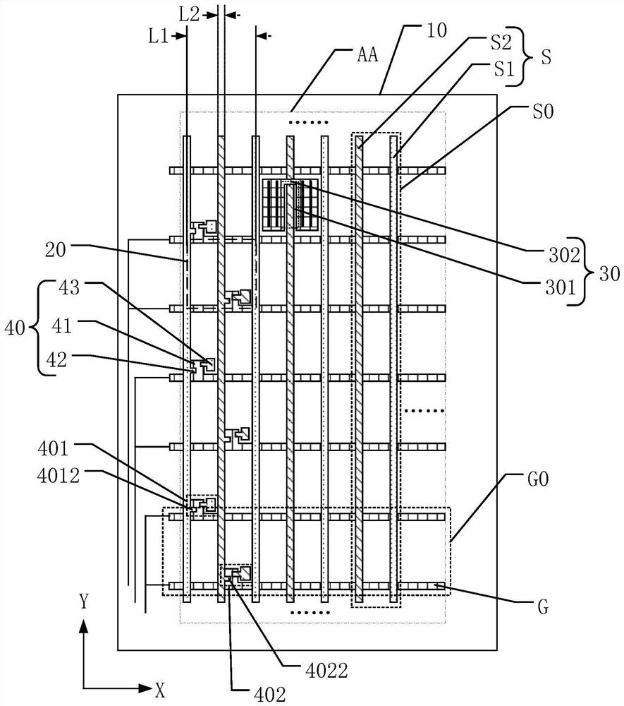
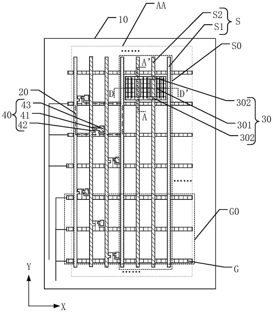
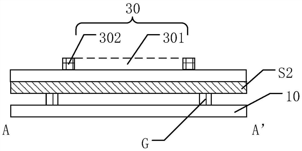
The invention discloses a display panel and a display device. The display panel includes a base substrate and a plurality of pixel units located on the base substrate; it also includes a plurality of scanning line groups and a plurality of data line groups, and each scanning line group includes At least two scanning lines, each data line group includes at least one main data line and at least one auxiliary data line, the scanning line and the main data line are cross-insulated to define the area where a plurality of pixel units are located; the scanning lines of each scanning line group The pixel unit includes a pixel electrode and at least one thin film transistor; in the direction perpendicular to the base substrate, in a pixel unit, the pixel electrode at the position of the auxiliary data line is provided with a hollowed out part and at least one connection part. In a direction perpendicular to the display panel, the auxiliary data line overlaps the hollow part. The display device includes the above-mentioned display panel. The present invention can not affect the display quality and pixel density, but also can realize narrow frame.

Description

technical field [0001] The present invention relates to the field of display technology, and more particularly, to a display panel and a display device. Background technique [0002] E-paper display is a flat-panel display technology with similar paper display performance. E-paper is becoming more and more popular in the market due to its low energy consumption, soft display effect similar to paper, and the prospect of being able to replace paper. Excellent retention characteristics are ideal for static display products such as text reading. Therefore, the electronic paper display panel has a huge application space in the fields of electronic readers (e-books), electronic price tags, industrial instruments, dynamic display billboards, and media products. [0003] The basic principle of electronic paper is that there are charged particles in the electrophoretic fluid. These charged particles can reflect the ambient light, and the image displayed by the paper is received by t...

Claims


Application Information

Patent Timeline
Patent Type & Authority Patents(China)
IPC IPC(8): G02F1/167G02F1/1685G02F1/1362G02F1/1368G02F1/1343H01L27/12
CPCG02F1/134309G02F1/136286G02F1/1368G02F1/167H01L27/124H01L27/1255
Inventor 许文钦席克瑞毛琼琴李金玉
Owner SHANGHAI TIANMA MICRO ELECTRONICS CO LTD
Why Eureka
Try Eureka