Dielectric filter

A dielectric filter and dielectric resonator technology, applied in waveguide devices, resonators, electrical components, etc., can solve the problems of weak filter out-of-band suppression, occupying a large axial space, unfavorable filter layout, etc., to achieve Effects of improving out-of-band rejection, reducing occupancy, and improving filtering performance

Pending Publication Date: 2019-01-18
江西一创新材料有限公司
View PDF9 Cites 10 Cited by
  • Summary
  • Abstract
  • Description
  • Claims
  • Application Information

AI Technical Summary

Problems solved by technology

The existing hybrid dielectric filter, as shown in the Chinese invention patent "Authorized announcement number: CN 103972621 B, authorized announcement date: October 05, 2016, name: a mixed dielectric waveguide filter", has the following defects: 1. Only one transmission zero point is generated in the three-mode resonator, the out-of-band rejection of the filter is weak, and the filtering performance is poor; Facilitate the placement of filters

Method used


Image

  • Dielectric filter
  • Dielectric filter
  • Dielectric filter

Examples


Embodiment Construction

[0018] The present invention will be further described below with reference to the drawings and specific embodiments (the central axis in this document refers to the central axis of the filter).

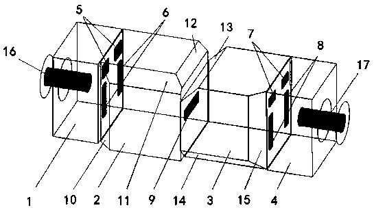
[0019] Such as figure 1 As shown, a dielectric filter includes a first single-mode dielectric resonator 1, a first three-mode dielectric resonator 2, a second three-mode dielectric resonator 3, and a second single-mode dielectric resonator that are sequentially fixedly connected in a straight line 4, the four dielectric resonators are cube-like dielectric resonators with a ceramic dielectric inside and a metal conductive layer on the outside. The axial lengths of the first single-mode dielectric resonator 1 and the second single-mode dielectric resonator 4 are 1 / 4~1 / 2 of the length of the other two sides, the lengths of the three sides of the first three-mode dielectric resonator 2 and the second three-mode dielectric resonator 3 are approximately equal.

[0020] The bonding surface...


PUM


Abstract

A dielectric filter comprises four cube-like dielectric resonators with a metal conductive layer attached to an outer surface of a ceramic dielectric, wherein the four dielectric resonators are connected in a straight line sequentially and fixedly. The front and rear dielectric resonators are single-mode dielectric resonators, and the middle two dielectric resonators are three-mode dielectric resonators. The edges of the three-mode dielectric resonators are provided with tangent angles which can generate cross-coupling. A pair of main coupling windows and a pair of cross-coupling windows are arranged between each single-mode dielectric resonator and the adjacent three-mode dielectric resonators. Each of the three-mode dielectric resonators and the single-mode resonator can produce two transmission zeros, which can improve the out-of-band rejection of the filter and the filtering performance of the filter. At the same time, it provides technical support for the adjacent arrangement of two three-mode dielectric resonators to reduce the volume of the filter.

Description

technical field [0001] The invention relates to a dielectric filter and belongs to the technical field of electronic components in the communication field. Background technique [0002] In recent years, with the increasing demand for high performance and miniaturization of communication equipment, dielectric filters have received more and more attention. The existing hybrid dielectric filter, as shown in the Chinese invention patent "Authorized announcement number: CN 103972621 B, authorized announcement date: October 05, 2016, name: a mixed dielectric waveguide filter", has the following defects: 1. Only one transmission zero point is generated in the three-mode resonator, the out-of-band rejection of the filter is weak, and the filtering performance is poor; Facilitate the placement of filters. Contents of the invention [0003] The present invention aims at the above-mentioned defects of the existing mixed-mode filter, and provides a new mixed-mode dielectric filter, ...

Claims


Application Information

Patent Timeline
Patent Type & Authority Applications(China)
IPC IPC(8): H01P1/20H01P7/10
CPCH01P1/2002H01P7/105
Inventor 王平
Owner 江西一创新材料有限公司
Why Eureka
Try Eureka