Helical reflective antenna and high power capacity array and transmitting system formed by the helical reflective antenna

A reflective antenna and helical antenna technology, applied in specific array feeding systems, antenna arrays, antenna arrays that are individually powered, etc., can solve the problems of complex feeding networks, limited bandwidth performance, low antenna utilization, etc. The effect of high capacity, increased bandwidth and high efficiency

Pending Publication Date: 2019-01-18
SOUTHWEST JIAOTONG UNIV
View PDF8 Cites 6 Cited by
  • Summary
  • Abstract
  • Description
  • Claims
  • Application Information

AI Technical Summary

Problems solved by technology

[0006] When the scale of the array increases, the forced feeding method will become particularly complicated, and problems such as feeding loss will be extremely prominent, especially in the high frequency band, which seriously limits its bandwidth performance and results in extremely low utilization of the antenna.

Method used


Image

  • Helical reflective antenna and high power capacity array and transmitting system formed by the helical reflective antenna
  • Helical reflective antenna and high power capacity array and transmitting system formed by the helical reflective antenna
  • Helical reflective antenna and high power capacity array and transmitting system formed by the helical reflective antenna

Examples


Embodiment 1

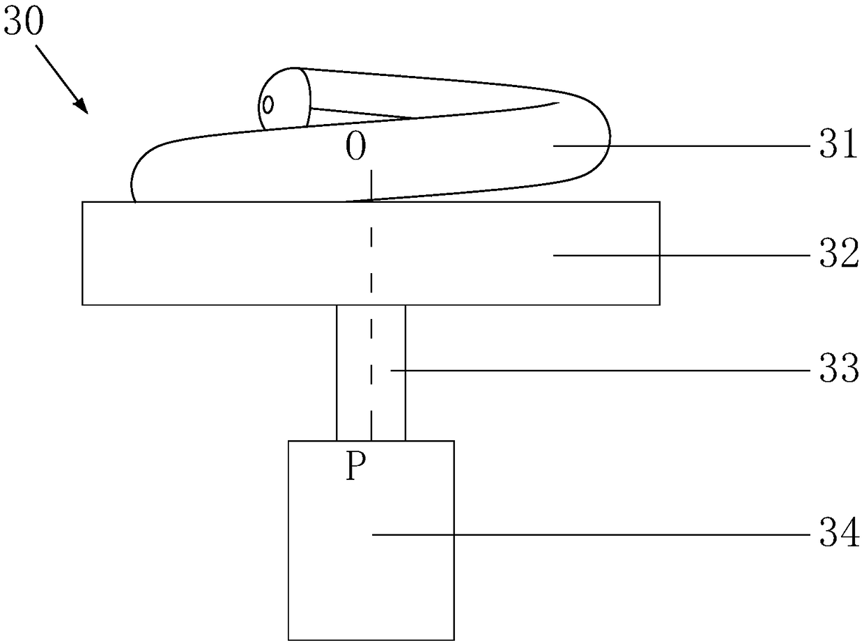
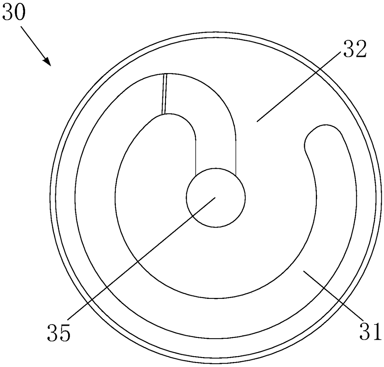
[0104] The structure of the helical reflector antenna 30 in this example is as follows: figure 1 and figure 2 As shown, it includes a reflecting surface 32 , a helical antenna 31 and a rotating mechanism 34 .

[0105] In this example, the reflecting surface 32 is cylindrical with an open top surface, and the radius of the cylindrical bottom surface is greater than the radius of the base circle of the helical antenna. The helical antenna 31 is placed in front of the reflecting surface, so that a part of the helical antenna is placed in the cylindrical cavity.

[0106] This reflective surface can improve the reflection coefficient, and the mutual interference between the helical reflective antennas can be reduced after forming an array.

[0107] In this example, the helical antenna 31 adopts a two-stage structure, and the helical antenna 31 is coaxial with the support shaft 33, such as figure 1 The central axis OP is shown.

[0108] In this example, the starting point of the...

Embodiment 2

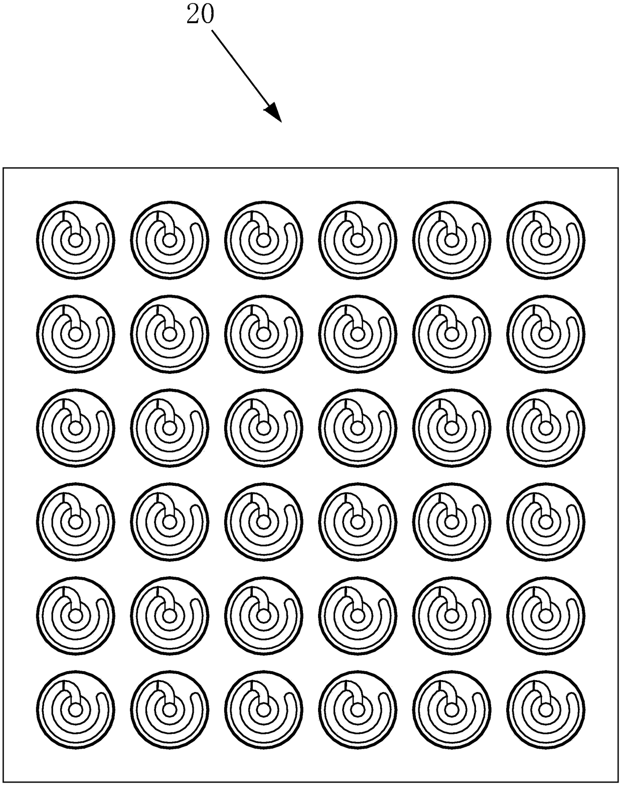
[0112] Such as image 3 As shown, the high-power-capacity helical reflective antenna array 20 in this example is a 6×6 planar matrix, which is composed of 36 helical reflective antennas 30 as array elements, and the motors in the rotating mechanisms of the 36 array elements are coordinated by the same control system And control, the electromagnetic wave directional radiation or scanning radiation of the helical reflective antenna array can be realized.

[0113] For the structure of the helical reflective antenna in this example, refer to the description of Embodiment 1.

Embodiment 3

[0115] The helical reflective antenna used in the high power capacity helical reflective antenna array 20 in this example is the same as that in Embodiment 2, and this example is also a planar array composed of 36 helical reflective antennas 30 .

[0116] The difference of the high power capacity helical reflective antenna array in this example is that the helical reflective antennas in the array are arranged in different ways. features such as Figure 4 shown.


PUM


Abstract

The present invention relates to helical antenna technology. The invention discloses a helical reflective antenna and a high-power capacity array and a transmitting system formed by the helical reflective antenna. A helical reflective antenna for reflecting electromagnetic waves, comprising a reflective surface, a helical antenna and a rotating mechanism; The helical antenna is arranged in front of the reflection and fixed on a support shaft; The helical antenna is coaxial with the support shaft, and the starting point thereof is located on the support shaft axis; The supporting shaft is connected with a rotating mechanism; The rotating mechanism is used for driving the support shaft to rotate and adjusting the phase of the reflected electromagnetic wave. A high-power-capacity helical reflective antenna array is composed of the helical reflective antennas arranged in an array. The high-power-capacity helical reflective antenna transmitting system of the present invention is composed ofthe high-power-capacity helical reflective antenna array and a feed source. The invention improves the bandwidth of the high-power microwave radiation antenna, and has the characteristics of flexiblearray, easy conformal and the like.

Description

technical field [0001] The present invention relates to the helical antenna technology, in particular to the helical antenna feeding technology, in particular to a helical reflective antenna and the high power capacity array and transmitting system formed therefrom. Background technique [0002] Helical antennas can be divided into planar helical antennas and three-dimensional helical antennas. The three-dimensional helical antenna can be divided into cylindrical helical antennas, conical helical antennas, etc. according to the winding shape. The present invention mainly relates to three-dimensional helical antennas, which are collectively referred to as helical antennas hereinafter. [0003] Helical antennas are widely used, especially in the field of high-power microwave transmission. The microwave antenna system composed of various helical antennas is the core of the microwave transmission system with high power capacity. In order to expand the power capacity, several h...

Claims


Application Information

Patent Timeline
Patent Type & Authority Applications(China)
IPC IPC(8): H01Q1/12H01Q1/36H01Q1/50H01Q3/32H01Q19/12H01Q21/00H01Q21/06
CPCH01Q1/12H01Q1/36H01Q1/50H01Q3/32H01Q19/12H01Q21/0018H01Q21/061
Inventor 李相强孔歌星张健穹王庆峰
Owner SOUTHWEST JIAOTONG UNIV
Why Eureka
Try Eureka