
Vibration type dust collecting and massage ground mat

A vibrating floor mat technology, applied in the field of hardware, can solve the problems that the floor mat cannot achieve the dust removal effect, increase the cost of maintenance, and easily breed mold, etc., and achieve the effect of strong functionality, reduced maintenance costs, and reasonable structure settings

Active Publication Date: 2019-01-22
嵊州市鉴亭新材料科技有限公司
View PDF6 Cites 2 Cited by
  • Summary
  • Abstract
  • Description
  • Claims
  • Application Information

AI Technical Summary

Problems solved by technology

[0003] 1. The dust removal method of the floor mat is the friction method. The dust and debris at the bottom of the object are retained on the surface of the mat through the relative friction between the surface of the mat and the bottom surface of the contact object. However, this dust removal method is relatively passive. When the place where the dust sticks is not in contact with the floor mat, the floor mat cannot achieve the dust removal effect, resulting in the failure of dust removal;
[0004] 2. The surface of the floor mat usually retains a lot of dust, which is easy to breed mold, so it needs to be changed frequently, which increases the cost of maintenance

Method used


Image

  • Vibration type dust collecting and massage ground mat
  • Vibration type dust collecting and massage ground mat
  • Vibration type dust collecting and massage ground mat

Examples


Embodiment Construction

[0025] The following will clearly and completely describe the technical solutions in the embodiments of the present invention with reference to the accompanying drawings in the embodiments of the present invention. Obviously, the described embodiments are only some, not all, embodiments of the present invention. Based on the embodiments of the present invention, all other embodiments obtained by persons of ordinary skill in the art without making creative efforts belong to the protection scope of the present invention.

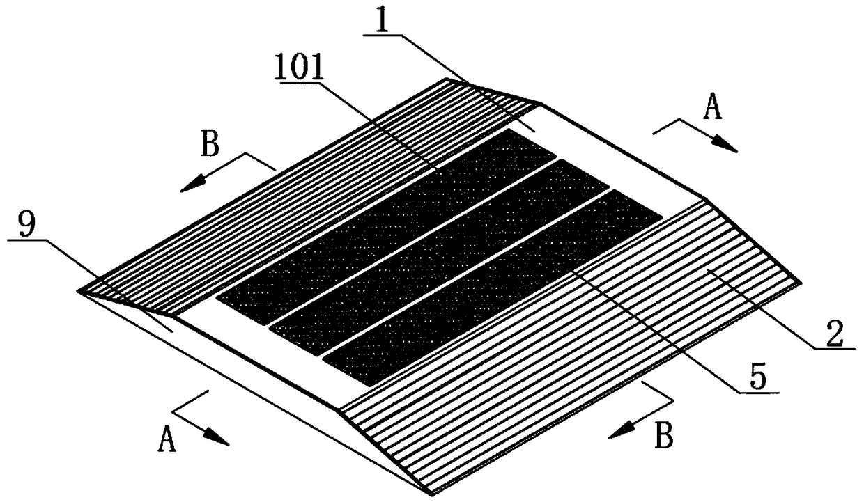
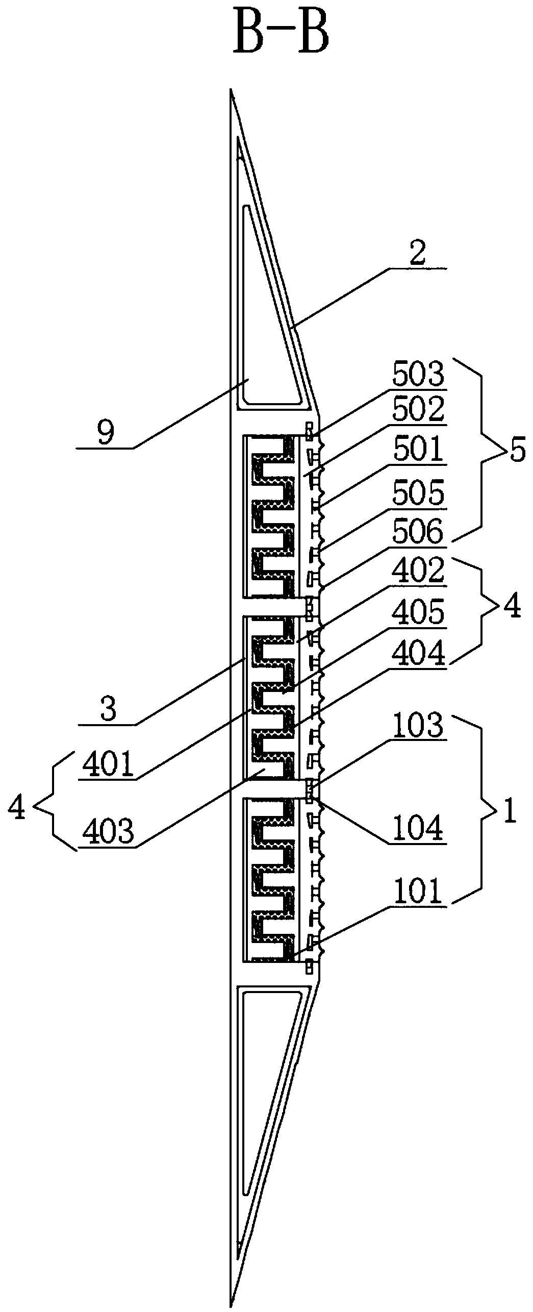
[0026] see Figure 1-5 , the present invention provides a technical solution: a vibrating dust-removing massage floor mat, including a supporting mechanism, a vibrating mechanism and a dust collecting mechanism set in the supporting mechanism, the supporting mechanism consists of an intermediate support frame 1 and an intermediate support frame 1 The side support frame 2 with a right-angled cavity structure set symmetrically on the front and rear sides is comp...


PUM


Abstract

The invention discloses a vibration type dust collecting and massage ground mat. The vibration type dust collecting and massage ground mat comprises a support mechanism, as well as a vibration mechanism and a dust collection mechanism which are arranged in the support mechanism, wherein the support mechanism is composed of a middle support frame in a framework structure and side support frames inright-angle-shaped cavity structures which are symmetrically arranged on the front and rear sides of the middle support frame, and three mounting grooves I in square groove structures are uniformly distributed at the upper end of the middle support frame; vibrators drive vibration plate groups and dust collecting and massage mats arranged at the upper ends of the vibration plate groups to performsynchronous vibration, thus the surfaces of objects contacting the dust collecting and massage mats also vibrate, then dust on the surfaces of the objects is separated from the objects, and the vibration type dust collection has relatively high dust collection efficiency; and through the dust collection mechanism, dust at the upper ends of the dust collecting and massage mats is sucked into a dustcollecting box, thus the purpose of dust collection is achieved, therefore, no accumulation of dust exists on the surfaces of the dust collecting and massage mats, so that the dust collecting and massage mats do not need to be replaced for washing, and finally, the maintenance cost is reduced.

Description

technical field [0001] The invention relates to the technical field of hardware, in particular to a vibrating dust-removing massage floor mat. Background technique [0002] The floor mat is a product that can effectively scrape off dirt and water at the entrance and keep the indoor floor tidy. The floor mat is divided into loop wire type, Z-shaped, concave-convex type, modular type, and aluminum alloy floor according to the appearance shape. Mats and carpet floor mats, among which the aluminum alloy floor mat is easy to clean, has good anti-skid, dust removal, flame retardant, anti-aging, high temperature resistance and other advantages, so it is very popular, but it still has the following disadvantages in actual use: [0003] 1. The dust removal method of the floor mat is the friction method. The dust and debris at the bottom of the object are retained on the surface of the mat through the relative friction between the surface of the mat and the bottom surface of the conta...

Claims


Application Information

Patent Timeline
IPC IPC(8): A47G27/02B08B7/02B08B5/04A61H23/00A61H39/04
CPCA47G27/0206A47G27/0243A61H23/00A61H39/04A61H2201/0134A61H2205/125B08B5/04B08B7/02
Inventor 姚屠乾何永萍王亚超
Owner 嵊州市鉴亭新材料科技有限公司
Learn More