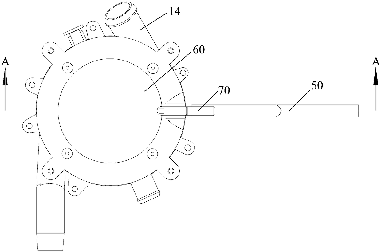
Material cleaning device and cooking appliance
A technology for cleaning devices and cooking utensils, applied to cooking utensils, household utensils, kitchen utensils, etc., can solve problems such as the impact of sewage structure, and achieve the effects of avoiding rice grain residues, ensuring sewage effect, and convenient installation.
- Summary
- Abstract
- Description
- Claims
- Application Information
AI Technical Summary
Problems solved by technology
Method used
Image
Examples
Embodiment 1
[0092] Embodiment one (not shown in the figure)
[0093] The sealing assembly 20 includes a discharge valve adapted to the shape of the discharge port, and the discharge valve is connected to the output end of the cleaning inlet pipe 70 .
[0094] Further, the sealing assembly 20 also includes a sealing sleeve, the sealing sleeve is sleeved on the output end of the cleaning inlet pipe 70, and is covered on the discharge valve; wherein, a reserved space is defined between the sealing sleeve and the discharge valve , and the sealing sleeve is provided with a through hole communicating with the reserved space, so that the airflow output by the cleaning inlet pipe 70 can reach the lower part of the cleaning chamber 10 .
[0095] Preferably, the discharge valve is a sealing ball, and the sealing ball is flexibly connected to the cleaning inlet pipe 70 .
[0096] Sealing assembly 20 comprises discharge valve, and the shape of discharge valve is adapted to the shape of discharge por...
Embodiment 2
[0107] Embodiment two (not shown in the figure)
[0108] The difference from Embodiment 1 is that the driving member includes a motor and a cam connected to the output shaft of the motor, and the cam abuts against the transmission member.
[0109] The transmission part is driven to rotate by the motor + the cam, and when the motor rotates, the long end or short end of the cam can be brought into contact with the transmission part, thereby realizing the pushing of the transmission part.
[0110]Specifically, the transmission member is arranged vertically, its lower end is against the cam, and its upper end is connected to the cleaning inlet pipe 70; when the short end of the cam contacts the transmission member, the transmission member is in a vertical state, and the ball valve closes the discharge port; When the cam rotates so that its long end contacts the transmission part, the lower end of the transmission part is pushed to move towards the direction of the cleaning cavity ...
Embodiment 3
[0111] Embodiment three (as figure 2 and Figure 4 shown)
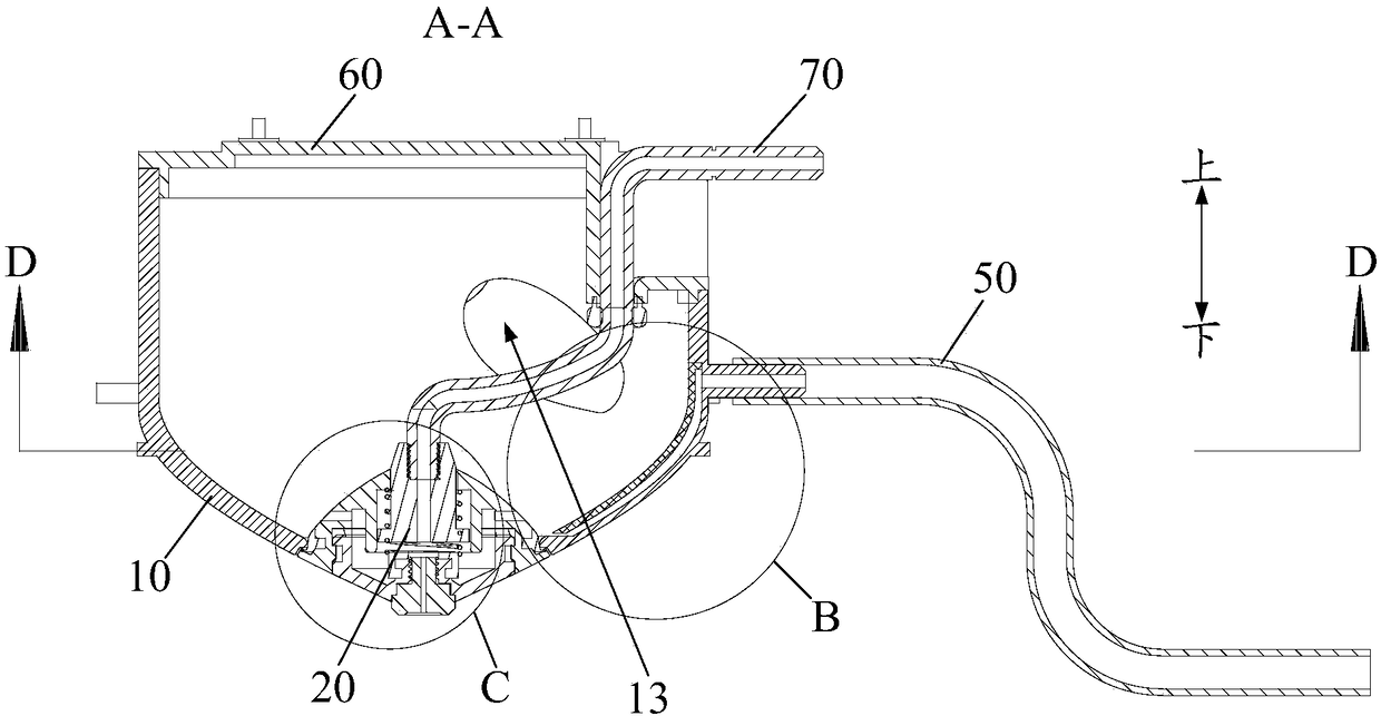
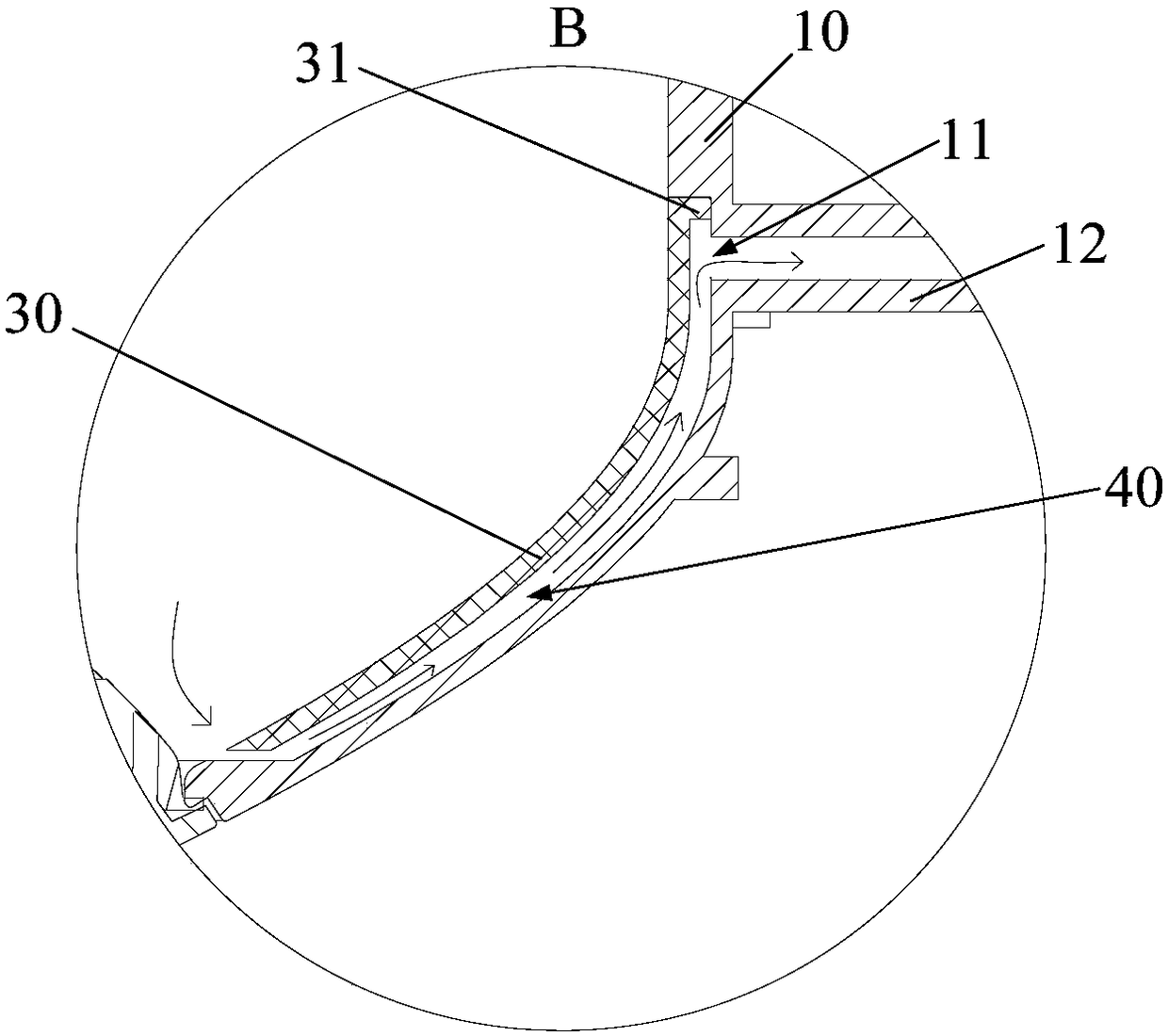
[0112] The sealing assembly 20 includes: a housing, a nozzle connector 23 and an atomizing nozzle 24 . Specifically, the shell is adapted to the shape of the discharge port; the nozzle joint 23 is installed on the top of the shell, and is connected to the output end of the cleaning inlet pipe 70, and communicates with the cleaning inlet pipe 70; the atomizing nozzle 24 is installed on the bottom of the shell , and set opposite to the nozzle joint 23, its water spray port is connected with the cooking chamber of the cooking appliance, and the atomizing nozzle 24 can move relative to the nozzle joint 23; wherein, when the cleaning inlet pipe 70 moves up and down, it can drive the shell up and down At the same time, it drives the nozzle joint 23 and the atomizing nozzle 24 to move relative to each other, so that when the shell closes the discharge port, the atomizing nozzle 24 is isolated from the nozzle joint 23, and...
PUM
 Abstract
Description
Claims
Application Information
 - R&D
- Intellectual Property
- Life Sciences
- Materials
- Tech Scout
- Unparalleled Data Quality
- Higher Quality Content
- 60% Fewer Hallucinations
Browse by: Latest US Patents, China's latest patents, Technical Efficacy Thesaurus, Application Domain, Technology Topic, Popular Technical Reports.
© 2025 PatSnap. All rights reserved.Legal|Privacy policy|Modern Slavery Act Transparency Statement|Sitemap|About US| Contact US: help@patsnap.com


