
Blade drilling device for electric fan

A drilling device and electric fan technology, applied in the direction of boring/drilling, drilling/drilling equipment, parts of boring machine/drilling machine, etc., can solve the problem of low efficiency of coolant use and achieve improved cooling efficiency and circulation The effect of high efficiency and increased volume

Inactive Publication Date: 2019-01-22
重庆市兴林电器有限公司
View PDF0 Cites 8 Cited by
  • Summary
  • Abstract
  • Description
  • Claims
  • Application Information

AI Technical Summary

Problems solved by technology

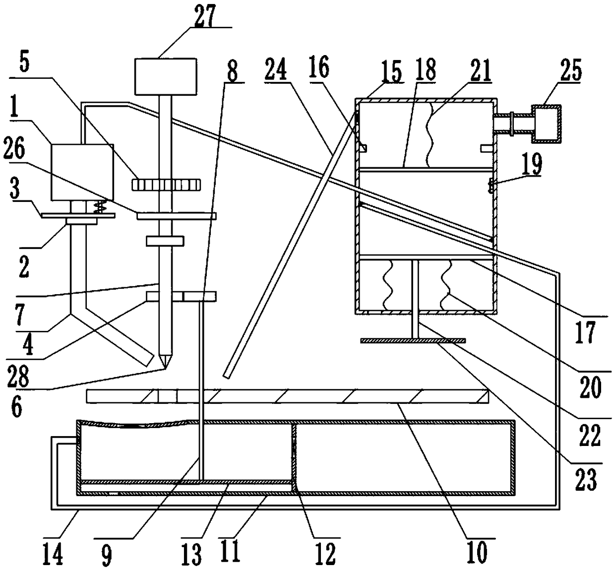
[0005] The present invention intends to provide a blade drilling device for an electric fan to solve the problem of low cooling liquid usage efficiency in the existing drilling device

Method used


Image

  • Blade drilling device for electric fan

Examples


Embodiment

[0025] A blade drilling device for an electric fan, such as figure 1 As shown, including the frame, the cooling box 1, the workbench 10 and the workbox 11 are fixed sequentially on the frame from top to bottom. The ratio of the cross-sectional area of ​​the upper surface of the workbox 11 to the workbench 10 is 5:3. The edge profile of the upper surface of the table 10 is wedge-shaped, and the top of the workbench 10 is provided with a drilling device fixed on the frame. The workbench is provided with a through hole positioned directly below the drilling device. Drill bit 6 and threaded rod 7, cylinder 27, motor 5, threaded rod 7 and drill bit 6 are arranged on the frame successively from top to bottom. The bottom of the cooling box 1 is connected with a liquid outlet pipe 4 with the nozzle facing the drill bit 6. The liquid outlet pipe 4 is coaxially connected with a rotary valve 2, and the rotary valve 2 is coaxially connected with a ring gear 3. The top of the rotary valve ...


PUM


Abstract

The invention relates to the technical field of turning, and discloses a blade drilling device for an electric fan. The blade drilling device comprises a frame, a cooling box, a worktable, a work chamber and a fixture box, a drilling device positioned on the upper portion of the worktable is arranged on the frame, the cooling box is communicated with a liquid outlet pipe, the drilling device is fixedly connected with a fixing block, the work chamber and the fixture box are positioned on the lower portion and the upper portion of the worktable, the upper surface of the work chamber is providedwith a collection opening, a first piston plate is vertically and slidably connected into the work chamber, a first connecting rod is fixedly connected between the first piston plate and the fixing block, a second piston plate is vertically and slidably connected into the fixture box, the side wall of the fixture box is fixedly connected with a heating device, a pressing block is vertically and slidably connected onto the frame, a second connecting rod is fixedly connected between the pressing block and the second piston plate, a second one-way liquid outlet valve is arranged on the side wallof the work chamber, and a cooling pipe is communicated between the second one-way liquid outlet valve and the cooling box. The blade drilling device is used for drilling fan blades, and cooling liquid can be timely supplemented.

Description

technical field [0001] The invention relates to the field of turning processing, in particular to a blade drilling device for an electric fan. Background technique [0002] The fan blade, namely the fan blade, is a component of a desk fan or a ceiling fan. The motor drives the fan blade to rotate, and the rotation of the fan blade can generate airflow. [0003] During use, a fan is generally used in combination with a plurality of fan blades and a rotor, so holes need to be drilled at the end of the fan blades close to the rotor to facilitate the installation of the fan blades on the rotor. The commonly used punching method is turning, specifically: fix the punched end of the fan blade on the workbench, and then punch the fan blade with a drilling device. In order to avoid damage to the drill bit due to overheating of the drill bit, coolant is usually sprayed on the drill bit to cool down. [0004] In order to prevent the waste of coolant, a coolant collection device is ge...

Claims


Application Information

Patent Timeline
Patent Type & Authority Applications(China)
IPC IPC(8): B23B41/00B23B47/00B23Q11/10
CPCB23B41/00B23B47/00B23Q11/10
Inventor 唐良兴
Owner 重庆市兴林电器有限公司
Learn More