Tubular part orifice deburring device

A technology for removing burrs and parts holes, which is applied in the field of processing parts grinding. It can solve the problems of affecting product quality, increasing the scrap rate, and high labor intensity. It achieves efficient and effective removal, simple and light structure, and avoids hard scratches.

Active Publication Date: 2019-01-25
LANDING GEAR ADVANCED MFG
View PDF2 Cites 4 Cited by
  • Summary
  • Abstract
  • Description
  • Claims
  • Application Information

AI Technical Summary

Problems solved by technology

At present, manual methods are often used to remove burrs from the orifice of cylindrical parts in mechanical processing, which has low removal efficiency, poor removal effect and high labor intensity.
[0003] CN207120121U discloses a polishing grinding head for the deburring of the orifice of the inner hole of the steel pipe, and CN207522241U discloses a self-cen

Method used


Image

  • Tubular part orifice deburring device
  • Tubular part orifice deburring device
  • Tubular part orifice deburring device

Examples


Embodiment

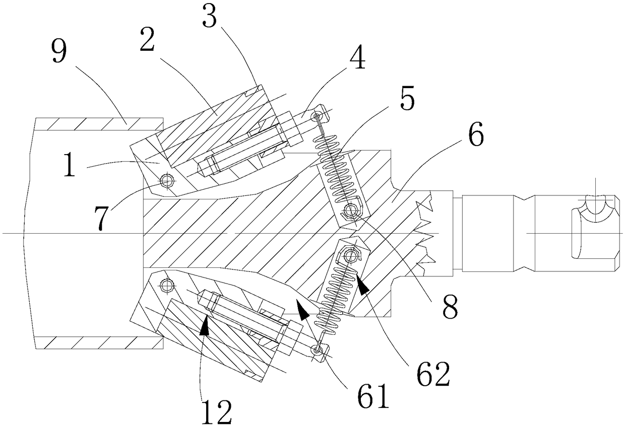
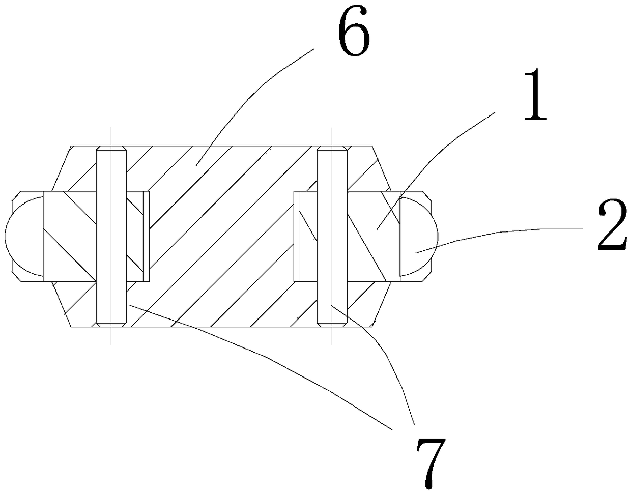
[0039] Such as Figure 1~3 As shown, the device for deburring the hole of the cylindrical part in this embodiment includes a file assembly, a spring 5 and a mounting part 6 that can rotate around the axis of the cylindrical part 9 .

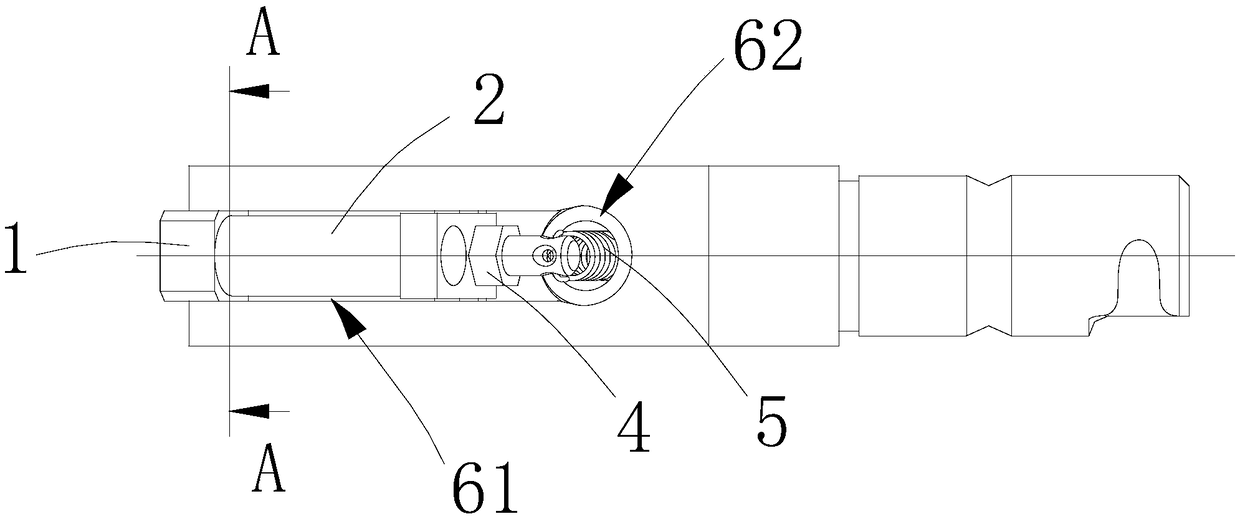
[0040] Such as Figure 4 As shown, the end surface of the mounting part 6 facing the opening of the cylindrical part 9 is provided with a knife groove 61 extending along the axial direction of the cylindrical part 9 .

[0041] The end of the file assembly facing the opening of the cylindrical part 9 extends into the knife groove 61 and is hinged with the mounting part 6 through the first pin 7, and the end of the file assembly facing away from the opening of the cylindrical part 9 extends out of the knife groove 61 and connects with the spring One end of 5 is fixedly connected, and a second hole 62 for accommodating the spring 5 is opened on the mounting part 6 , and the other end of the spring 5 extends into the second hole 62 and is fixed with...


PUM


Abstract

The invention discloses a tubular part orifice deburring device. The tubular part orifice deburring device comprises a file module, a spring and a mounting member capable of rotating around the axis of a tubular part; the end surface of the mounting member, which faces towards the orifice of the tubular part, is provided with a tool groove extending the axial direction of the tubular part; one endof the file module, which faces toward the orifice of the tubular part, extends into the tool groove and is hinged to the mounting member at a hinge point, one end of the file module, which backs tothe orifice of the tubular part, extends out of the tool groove and is fixedly connected to one end of the spring, and the other end of the spring is fixedly connected with the mounting member; the file module can swing around the hinge point, and inside the tool groove a yielding space for the file module to swing around the hinge point is formed. When the tubular part orifice deburring device isin work, the spring drives the file module to produce working pressure onto the orifice of the tubular part; due to the fact of being capable of flexibly rotating around the hinge point inside the tool groove and with the spring providing the rotating force, the file module can ensure high-efficiency and effective removal of burrs of the orifice of the tubular parts and meanwhile avoid hard scratching of the tubular part.

Description

technical field [0001] The invention belongs to the technical field of machining parts grinding, and in particular relates to a device for deburring holes of cylindrical parts. Background technique [0002] There are many burrs in the inner hole of the end surface of the cylindrical parts after the head is cut, and the hole burrs need to be dealt with. At this stage, manual methods are often used to remove burrs from the orifice of cylindrical parts in machining, which has low removal efficiency, poor removal effect and high labor intensity. [0003] CN207120121U discloses a polishing grinding head for the deburring of the orifice of the inner hole of the steel pipe, and CN207522241U discloses a self-centering polishing device for the deburring of the orifice of the inner hole of the steel pipe. However, the practice shows that the conical grinding head is in rigid contact with the part orifice, and it is easy to cause hard damage to the part orifice during the working proc...

Claims


Application Information

Patent Timeline
IPC IPC(8): B23D67/00
CPCB23D67/00
Inventor 胡阿林白亚玲樊智敏张一宏李振源鱼增学刘海莲方鹏
Owner LANDING GEAR ADVANCED MFG
Why Eureka
Try Eureka