Ball type automatic balance device for rotating machinery

An automatic balancing and rotating machinery technology, applied in the direction of non-rotating vibration suppression, manipulators, mechanical equipment, etc., can solve problems such as ball wear, lack of raceway oiling, unfavorable rotor use, etc., to avoid mechanical kinetic energy and facilitate maintenance and replacement Effect

Inactive Publication Date: 2019-01-25
东莞市奇趣机器人科技有限公司
View PDF0 Cites 1 Cited by
  • Summary
  • Abstract
  • Description
  • Claims
  • Application Information

AI Technical Summary

Problems solved by technology

[0004] The object of the present invention is to provide a kind of rolling-ball type automatic balancing device for rotating machinery, in order to solve the problem in the rolling-ball-type automatic balancing device for rotating machinery used in the above-mentioned background technology, there is lubricating fluid in the raceway, so as to ensure The normal operation of the rotor, but the ball-type automatic balancing device currently used does not have the function of filling the inside of the raceway, so that the balls will wear out due to high friction after a period of use, making the balls run poorly. Flexibility also reduces the automatic balancing ability of the rotor, which is not conducive to the subsequent use of the rotor

Method used


Image

  • Ball type automatic balance device for rotating machinery
  • Ball type automatic balance device for rotating machinery
  • Ball type automatic balance device for rotating machinery

Examples


Embodiment Construction

[0029] The technical solutions in the embodiments of the present invention will be clearly and completely described below in conjunction with the accompanying drawings in the embodiments of the present invention. Obviously, the described embodiments are only some of the embodiments of the present invention, and not all of them. The embodiments of the present invention and all other embodiments obtained by persons of ordinary skill in the art without making creative efforts belong to the protection scope of the present invention.

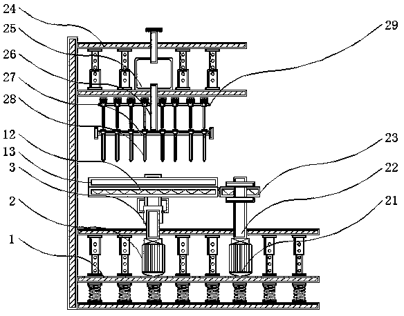
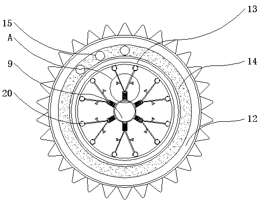
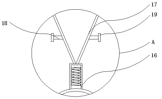
[0030] see Figure 1-7, the present invention provides a technical solution: a rolling ball type automatic balancing device for rotating machinery, including a shock absorbing base 1, a first driving motor 2, a smooth shaft 3, a connecting sleeve 4, a locking groove 5, and a locking block 6 , chute 7, slider 8, support rod 9, rotating part 10, fixed bar 11, first gear 12, rotor 13, slideway 14, rolling ball 15, elastic support 16, connecting bar 17, ...


PUM


Abstract

The invention discloses a ball type automatic balance device for rotating machinery. The ball type automatic balance device comprises a damping base, fixing bars, a slideway and a damping platform andis characterized in that a first drive motor is mounted on the left side inside the damping base, the output end flange of the first drive motor is connected with a smooth rotary shaft, a connectingsleeve is mounted at the upper end of the smooth rotary shaft, a second drive motor is mounted on the right side inside the damping base, a second gear is connected to the outer wall of a threaded rotary shaft in a threaded manner, and the damping platform is fixedly welded above the damping base. The ball type automatic balance device has the advantages that due to the fact that the outer walls of the smooth rotary shaft and a lock block and the inner walls of the connecting sleeve and a lock groove are threaded, the smooth rotary shaft is connected with the connecting sleeve in a threaded manner, the smooth rotary shaft can be conveniently and firmly connected with the connecting sleeve, and a second reinforcing lock can be provided for the connection between the smooth rotary shaft andthe connecting sleeve by the lock groove and the lock block which correspond to each other.

Description

technical field [0001] The invention relates to the technical field related to rotary machines, in particular to a rolling ball type automatic balancing device for rotary machines. Background technique [0002] Automatic balancing devices for rotating machinery are mainly divided into two types, one is microcomputer-controlled type, and the other is automatic centering type. The automatic centering type rotor automatic balancing device has simple structure, reliable operation, low cost, and does not need to provide external energy. , and can automatically adjust the rotor unbalance, etc., but it has the characteristics of increasing the unbalance of the rotor in the subcritical state, so that this type of automatic balancing device can only play a role when it must operate at a supercritical speed. The function of automatic balance, so there is the disadvantage that the balance cannot be adjusted at full speed, and the application has certain limitations. At present, it is m...

Claims


Application Information

Patent Timeline
Patent Type & Authority Applications(China)
IPC IPC(8): B25J19/00F16F15/04F16N11/06F16N21/00F16N33/00
CPCB25J19/0008B25J19/0054B25J19/0062B25J19/0091F16F15/04F16F2238/026F16N11/06F16N21/00F16N33/00
Inventor 郑海烈谢忠连王俊杰
Owner 东莞市奇趣机器人科技有限公司
Why Eureka
Try Eureka