Build-up force standard machine capable of realizing self-checking function

A superimposed, standard machine technology, applied in the calibration/testing of force/torque/power measuring instruments, weighing equipment testing/calibration, measuring devices, etc., can solve the problem of small measurement range, inability to check and correct data, and accurate To solve problems such as low accuracy level, achieve the effect of high accuracy level, low cost, and improve data accuracy

Pending Publication Date: 2019-01-25
山西省计量科学研究院
View PDF0 Cites 4 Cited by
  • Summary
  • Abstract
  • Description
  • Claims
  • Application Information

AI Technical Summary

Problems solved by technology

[0007] In order to solve the problems that the traditional superimposed force standard machine has low accuracy level, small measurement range, and cannot perform self-inspection and self-calibration of data, the present invention provides a superimposed force standard machine that can realize the self-check function
[0009] The present invention is mainly provided to solve the problems of low accuracy level, small measurement range, and the inability to self-examine and self-check the data. It mainly includes an oil cylinder seat and a moving beam. A 10MN standard sensor group is installed in the oil cylinder seat. 10MN The standard sensor group is connected with the external standard sensor instrument, and the oil cylinder is installed on the oil cylinder seat. The oil cylinder is connected with the external servo motor and servo oil pump through the reversing valve. The top of the oil cylinder is equipped with a back cap, and the bottom is equipped with a nut and a locking plate. 1. There is a piston inside. This structure is well sealed, and the leakage is basically zero during work. The upper part of the back cap is connected with the lead screw, and the upper part of the four lead screws is installed with a moving beam. A reducer bracket is installed in the center of the top installation. The moving beam drives the upper platen to move. According to the length of the screw, there is a certain stroke. The reducer is installed on the reducer bracket. The reducer is controlled by the computer, and the reducer is driven by the large and small sprockets. The moving beam moves up and down on the lead screw to adjust the height of the test space. The moving beam is connected to the four lead screws through screw nuts, washers, screw nut back caps and fastening discs. Large sprockets are installed on the four screw screws. , each large sprocket is equipped with a tensioning sprocket, the tensioning sprocket is installed on the tensioning wheel seat through the shaft, and the tensioning wheel seat is installed on the tensioning wheel adjustment seat, the tensioning wheel The adjustment seat is installed on the moving beam, and there are four small sprockets on the reducer, and each small sprocket is connected with the corresponding large sprocket through a chain or belt; the function of the tensioning sprocket is to adjust the small sprocket of the reducer The tightness of the connection with the large sprocket

Method used


Image

  • Build-up force standard machine capable of realizing self-checking function
  • Build-up force standard machine capable of realizing self-checking function
  • Build-up force standard machine capable of realizing self-checking function

Examples


Embodiment Construction

[0021] The present invention will be further described below in conjunction with specific examples.

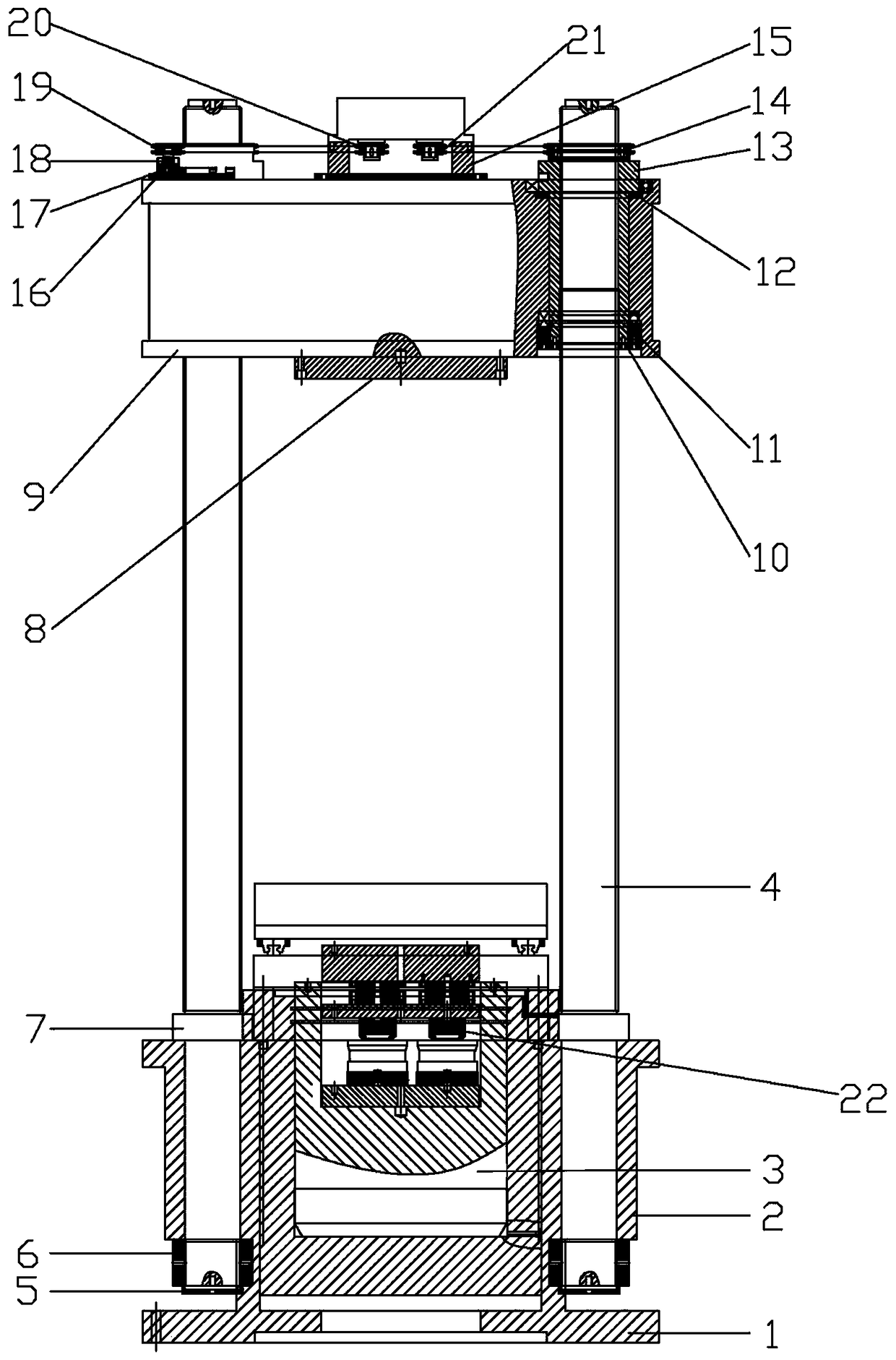
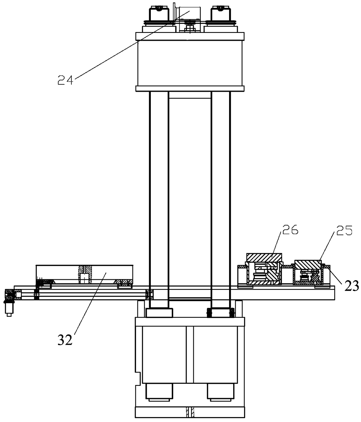
[0022] A superimposed force standard machine capable of self-checking function, such as Figure 1-Figure 2 As shown, it includes an oil cylinder base 1 and a moving beam 9. A 10MN standard sensor group 22 is installed in the oil cylinder base 1. An oil cylinder 2 is installed on the oil cylinder base 1. A back cap 7 is installed on the top of the oil cylinder 2, and a back cap 7 is installed on the bottom of the oil cylinder 2. There are nuts 6 and locking discs 5, and a piston 3 is arranged inside. The upper part of the back cap 7 is connected with the lead screw 4. The upper parts of the four lead screws 4 are equipped with a moving beam 9, and the center of the bottom of the moving beam 9 is installed with an upper Pressing plate 8, the center of top installation is equipped with reducer bracket 15, and on described reducer bracket 15, reducer 24 is installed, and described...


PUM


Abstract

The invention discloses a build-up force standard machine capable of realizing a self-checking function. The build-up force standard machine comprises an oil cylinder socket and a moving cross beam, wherein a 10MN standard sensor group is installed in the oil cylinder socket; an oil cylinder is installed on the oil cylinder socket; the top part of the oil cylinder is provided with a back cap, thebottom part is provided with a nut and a locking disc, a piston is arranged inside the oil cylinder, and the upper part of the back cap is connected with a lead screw; the moving cross beam is mountedon the upper part of the lead screw, an upper pressing plate is mounted at the center of the bottom part of the lead screw, and the center of the top part is provided with a speed reducer; and four minor chain wheels on the speed reducer are connected with corresponding large chain wheel by means of a chain or a belt; and a moving platform is arranged on the upper part of the oil cylinder socket,the moving platform comprises a linear guide rail and a workbench moving plate, the workbench moving plate is connected with a ball screw by means of a movable nut, the ball screw is connected with an output shaft of a servo motor, a workbench is mounted on the upper part of the workbench moving plate, a 3MN standard sensor group and a 1MN standard sensor group are arranged on the linear guide rail, and the 3MN standard sensor group and the 1MN standard sensor group are mounted on the same trolley moving assembly and are integrally connected with the workbench.

Description

technical field [0001] The invention relates to the technical field of force measurement and testing, in particular to a superimposed force standard machine capable of realizing self-checking function, which is applied in an environment where force data needs to be checked and checked by itself. Background technique [0002] The force standard machine is currently the most important force measuring device for verifying load cells, standard force gauges, force sensors, etc. Among them, the superimposed force standard machine has been favored by more and more people because of its large measuring range, relatively low price and many other advantages, and its application range is more and more extensive. According to the previous research results, the current status of similar research at home and abroad is as follows: The traditional superimposed force standard machine has the following shortcomings: [0003] 1. The accuracy level is low. From the current situation of the co...

Claims


Application Information

Patent Timeline
Patent Type & Authority Applications(China)
IPC IPC(8): G01L25/00G01G23/01
CPCG01G23/01G01L25/00
Inventor 韩剑高斐刘涛李爱伟
Owner 山西省计量科学研究院
Why Eureka
Try Eureka