Sinusoidal optical pressure sensitive coating dynamic pressure calibration chamber

A dynamic pressure, sinusoidal technology, applied in the direction of measuring fluid pressure, measuring devices, instruments, etc., to achieve the effect of easy processing, accuracy assurance and simple structure

Active Publication Date: 2019-01-25
NORTHWESTERN POLYTECHNICAL UNIV
View PDF11 Cites 7 Cited by
  • Summary
  • Abstract
  • Description
  • Claims
  • Application Information

AI Technical Summary

Benefits of technology

This patented technology describes an apparatus for accurately measuring static pressures applied over various surfaces such as films or other materials. It uses a special type called a rectangular tube which creates waves along its way through it. These waves help make accurate measurements even when there may have interferents between different parts of the device. By adjusting these parameters, this technique allows us to measure very small changes caused by external factors like temperature or humidity without affecting their effectiveness. Overall, this new method simplifies the manufacture of devices while improving their performance.

Problems solved by technology

This technical problem addressed in this patents relates to improving the precision and consistency required when accurately determining both pressure values and radiance levels within an automobile engine cylinder head gasket. Current solutions involve multiple components like impactors/strokes, fluid filled vapor cells, piezoelectric crystal transducers, and laser systems. These techniques require precise placement and may lead to reduced efficiency or even failure if they were applied outside their respective environments.

Method used


Image

  • Sinusoidal optical pressure sensitive coating dynamic pressure calibration chamber
  • Sinusoidal optical pressure sensitive coating dynamic pressure calibration chamber
  • Sinusoidal optical pressure sensitive coating dynamic pressure calibration chamber

Examples


Embodiment Construction

[0031] Now in conjunction with embodiment, accompanying drawing, the present invention will be further described:

[0032] The concrete technical scheme that the present invention adopts is:

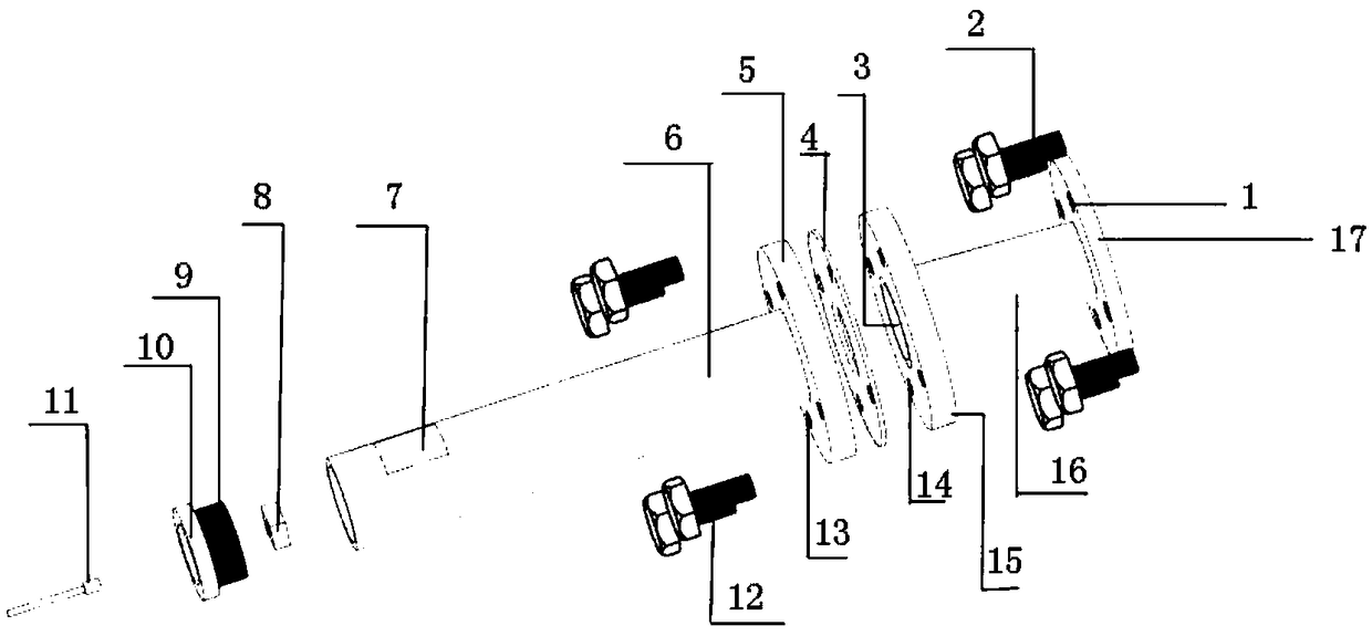
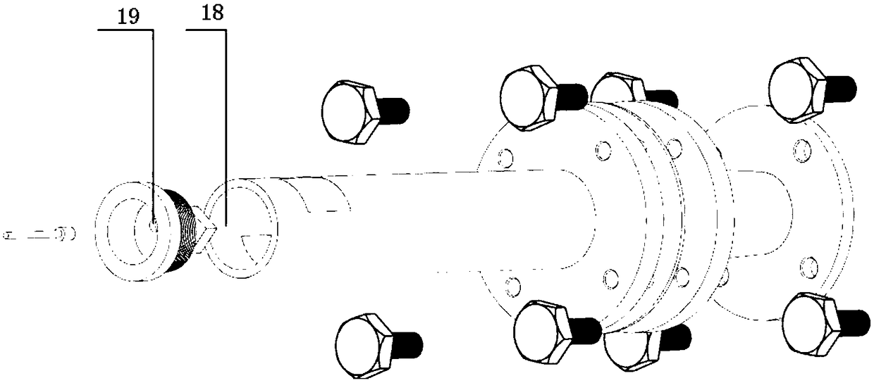
[0033] It is composed of the first flange 5, the second flange 15 and the third flange 17, the adapter section 16, the main body section 6, the bottom cover 10, the transparent window section 7, the sealing rubber ring 4, and the optical pressure-sensitive calibration sheet 8. Calibration cabin. The dynamic calibration test bench is composed of woofer / tweeter, dynamic calibration cabin, photomultiplier tube (PMT), pressure sensor, data acquisition card and host.

[0034] 1. The establishment of dynamic calibration cabin

[0035] a. Comparing the cut-off frequency formula of rectangular section In the case of polar symmetric vibration of the sound source, the cut-off frequency formula of the circular section Under the condition of the same cross-sectional area, the cut-off frequency...


PUM

PropertyMeasurementUnit
The inside diameter ofaaaaaaaaaa
Diameteraaaaaaaaaa
Small end diameteraaaaaaaaaa

Abstract

The invention relates to a sinusoidal optical pressure sensitive coating dynamic pressure calibration chamber, which is mainly used for pressure sensitive coating dynamic pressure calibration. In order to form a pressure environment capable of carrying out dynamic measurement, a calibration chamber body is divided into a switching section, a main body section and a bottom cover. All size design ofeach section is conducted according to corresponding principles. The main body section and the switching section are connected by means of a flange, the main body section and the bottom cover are connected by means of internal and external threads, and the bottom cover is assembled with an optical pressure sensitive calibration piece and a pressure sensor. In order to meet the demand for ultraviolet light of pressure sensitive coating pressure measurement, a piece of optical glass is arranged on the main body section of the calibration chamber to ensure a smooth optical path. The sinusoidal optical pressure sensitive coating dynamic pressure calibration chamber breaks through the limitation of an upper limit of 10 kHz frequency of optical pressure sensitive dynamic calibration of Tohoku University in Japan in 2017, performs optical pressure sensitive dynamic calibration on each wavelength band below 19 kHz through changing lengths of the main body section and the switching section, and achieves the world-class advanced level. The sinusoidal optical pressure sensitive coating dynamic pressure calibration chamber is simple in structure and convenient to process, has high anti-interference capability, and can effectively reduce the experimental cost.

Description


Claims


Application Information

Patent Timeline
Owner NORTHWESTERN POLYTECHNICAL UNIV
Why Eureka
Try Eureka