Analysis method for studying rock joint surface shearing damage process and test system

A technology of rock joints and shear failure, which is applied in the direction of applying stable shear force to test the strength of materials, analyze materials, and measuring devices, etc. It can solve the problem of single shear failure process of joint surfaces, unable to continuously monitor and accurately obtain natural joints Deformation and failure laws and eigenvalues ​​within the surface, systematic research on the shear failure process of unfavorable rock joint surfaces, etc., to achieve the effect of accurate positioning and promotion of displacement and deformation

Inactive Publication Date: 2019-01-25
SHANDONG UNIV OF SCI & TECH
View PDF0 Cites 21 Cited by
  • Summary
  • Abstract
  • Description
  • Claims
  • Application Information

AI Technical Summary

Problems solved by technology

Laboratory tests are the most direct means to study the evolution of joint surface morphology and mechanical properties during the joint shear process. However, in the existing test devices and methods, it is impossible to perform high-precision repeated tests on rock specimens with natural joints. It is also impossible to continuously monitor and accurately obtain the internal deformation and failure laws and eigenvalues ​​of natural joint surfaces
In addition, the current research on the joint surface shear test is often a single aspect of the joint surface shear failure process, and there are few methods and techniques for comprehensive research on the joint surface shear failure process, which is not conducive to the study of the joint surface shear failure process. Systematic research on shear failure process of rock joints

Method used


Image

  • Analysis method for studying rock joint surface shearing damage process and test system
  • Analysis method for studying rock joint surface shearing damage process and test system
  • Analysis method for studying rock joint surface shearing damage process and test system

Examples


Embodiment 1

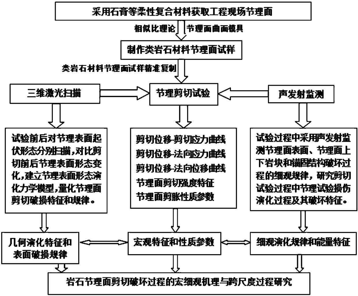
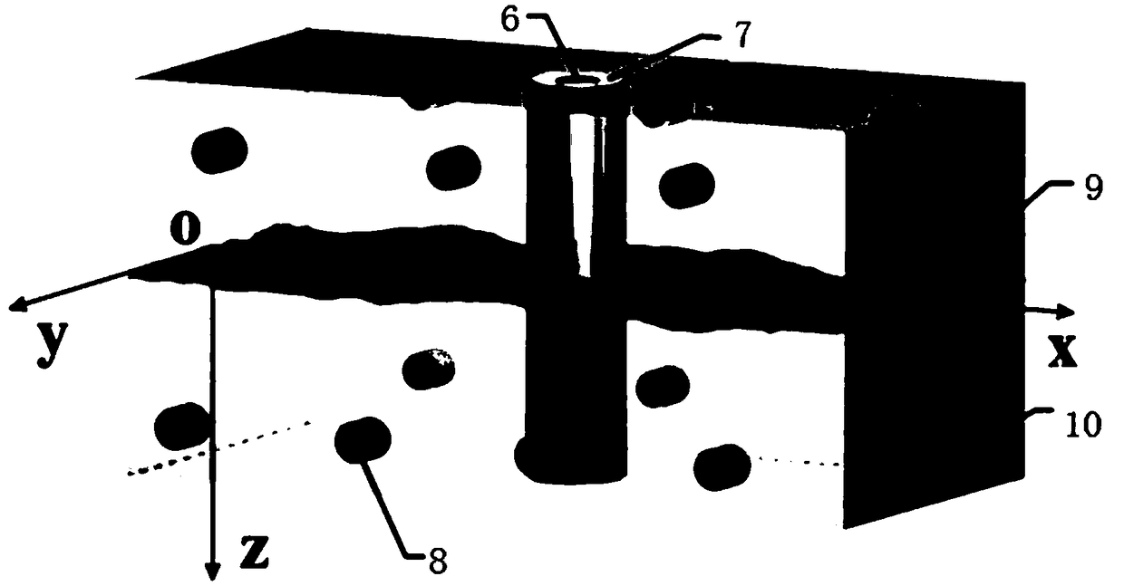
[0052] The embodiment of the present application provides a test system for studying the shear failure process of rock joint surfaces. The test system includes: joint surface laser scanner, joint shear box, rock joint shear loading structure, joint surface shear failure process acoustic launch monitor.

[0053] The joint shear box is used to place the specimen.

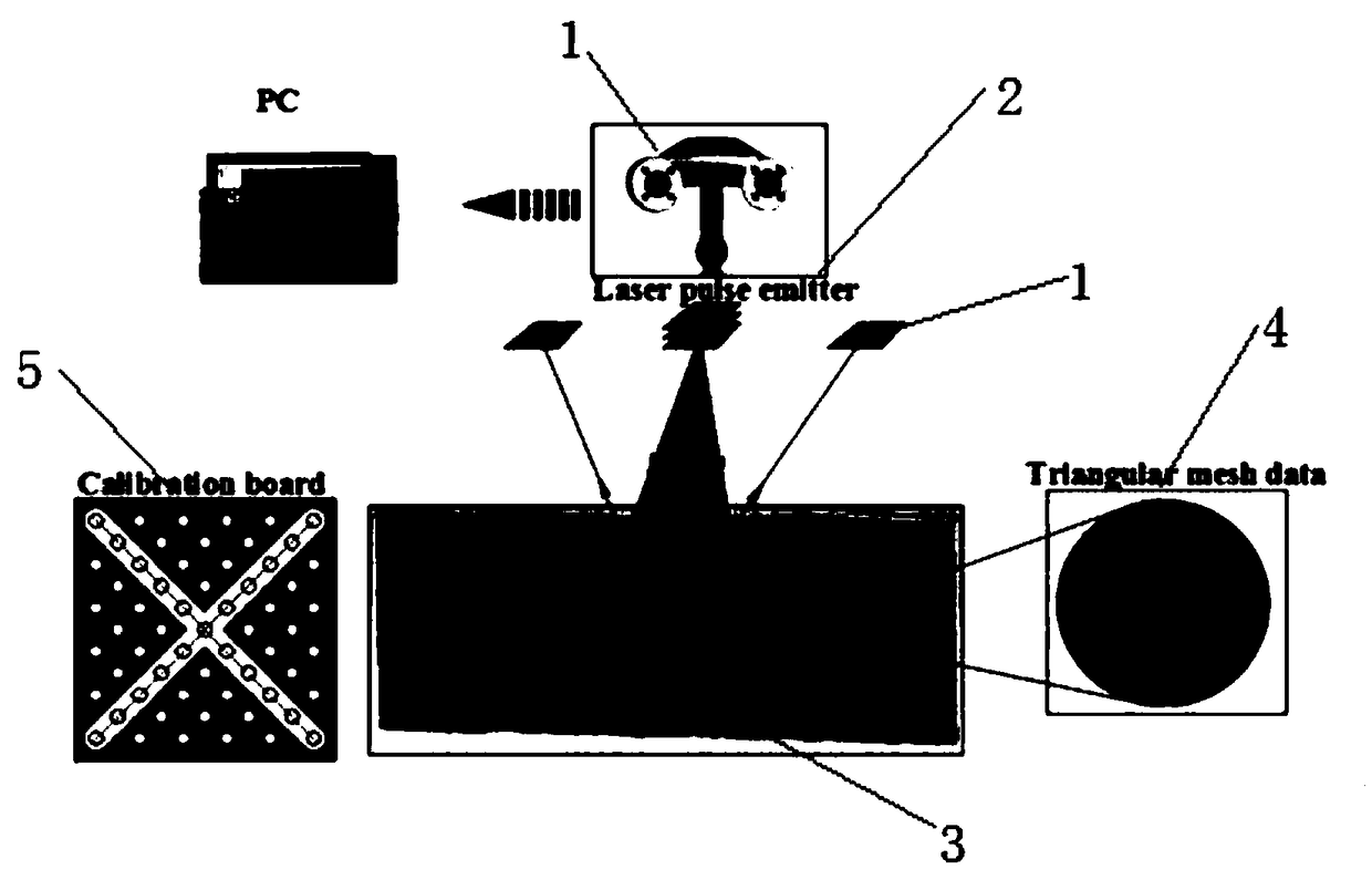
[0054] The joint surface laser scanner is used to perform laser scanning on the rock joint surface to obtain the characteristic information of the joint surface morphology. Before the acquisition of the joint surface morphology, the laser scanner needs to be calibrated first, and the scanning can be performed after optimization. The scanning mainly calculates the distance by the time from the laser emission to the return from the side object, and synchronously measures the laser pulse value to generate data. After the scanning is completed, the scanned data position set can be exported, and the data in the height dir...


PUM


Abstract

The invention discloses an analysis method for studying the rock joint surface shearing damage process and a test system. The method comprises the following steps of using a mold taking material to rub and print the surface form of a natural rock joint surface; making a rock-like material test sample with the same surface form and mechanical parameter as natural rock by using a natural rock jointcurve surface mold; controlling different boundary conditions on the test samples to perform rock joint shearing tests, thus obtaining joint surface shearing macroscopic property parameter and featurevalues; in the shearing test process, using the sound emission to monitor the microcosmic evolution rule and energy features of the damage process of the surface of the joint surface, joint surface upper and lower rock block and anchoring structures; performing joint surface scanning by a three-dimensional laser scanning instrument before and after the shearing test, thus obtaining geometric evolution features of the joint surface damage; precisely expressing the damage property of the joint surface in the shearing process and the quantitative characterization thereof by combining the macroscopic property parameter and feature values of the joint surface shearing, the microcosmic evolution rule of the damage process, the energy features and the geometric evolution features.

Description

technical field [0001] The present disclosure generally relates to the field of underground engineering tests, and in particular relates to an analysis method and a test system for studying the shear failure process of rock joint surfaces. Background technique [0002] Entering the 21st century, my country's tunnel and underground engineering construction has entered an unprecedented period of prosperity, and more and more transportation, water conservancy and hydropower, mining and other projects are inevitably built in jointed rock mass areas. Engineering accidents such as sustained large deformation and large-volume landslides induced by shear failure of jointed rock often occur. Compared with the complete rock block, the joint surface has lower shear strength and is the weakest surface in the rock mass. Therefore, the mechanical properties of the rock mass largely depend on the shear mechanical properties of the joint surface. [0003] In actual engineering, many factor...

Claims


Application Information

Patent Timeline
Patent Type & Authority Applications(China)
IPC IPC(8): G01N3/24G01N3/06
CPCG01N3/24G01N3/06G01N3/068G01N2203/0025G01N2203/0647G01N2203/0658
Inventor 王刚肖智勇张振松蒋宇静
Owner SHANDONG UNIV OF SCI & TECH
Why Eureka
Try Eureka