A developer receiving container

A developer and container body technology, applied in the direction of instruments, electrical recording, optics, etc., can solve the problems of uneven feeding, large heat generation, complex structure, etc., to avoid large contact area, reduce frictional heat generation, Effect of Residue Reduction

Active Publication Date: 2019-01-25
JIANGXI KAILIDE TECH CO LTD
View PDF5 Cites 0 Cited by
  • Summary
  • Abstract
  • Description
  • Claims
  • Application Information

AI Technical Summary

Problems solved by technology

The current toner cartridge has a rotatable stirring shaft inside, and the stirring shaft generally plays the role of transporting toner (ie developer). Most of them have the defect of uneven feeding. In addition, the contact area between the spiral blade and the carbon powder is too large, resulting in excessive frictional heat generation between the carbon powder and the spiral blade.
In addition, there is currently another solution for toner transmission: a developer container with a movable push plate, a screw working assembly is formed between the movable push plate and the rotating shaft, and when the rotating shaft rotates, the movable push plate moves along the The inner cavity of the container moves to send the toner to the powder outlet; the structure of this scheme is more complicated, and during the moving process of the moving push plate, the friction between the moving push plate and the inner wall of the container is relatively large, resulting in too hot

Method used


Image

  • A developer receiving container
  • A developer receiving container
  • A developer receiving container

Examples


Embodiment Construction

[0021] Embodiments of the present invention are described in detail below, examples of which are shown in the drawings, wherein the same or similar reference numerals designate the same or similar elements or elements having the same or similar functions throughout. The embodiments described below by referring to the figures are exemplary and are intended to explain the present invention and should not be construed as limiting the present invention.

[0022] The present invention will be further described in detail below through specific embodiments in conjunction with the accompanying drawings. Please refer to attached picture.

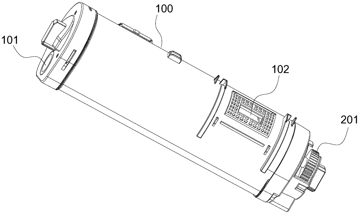
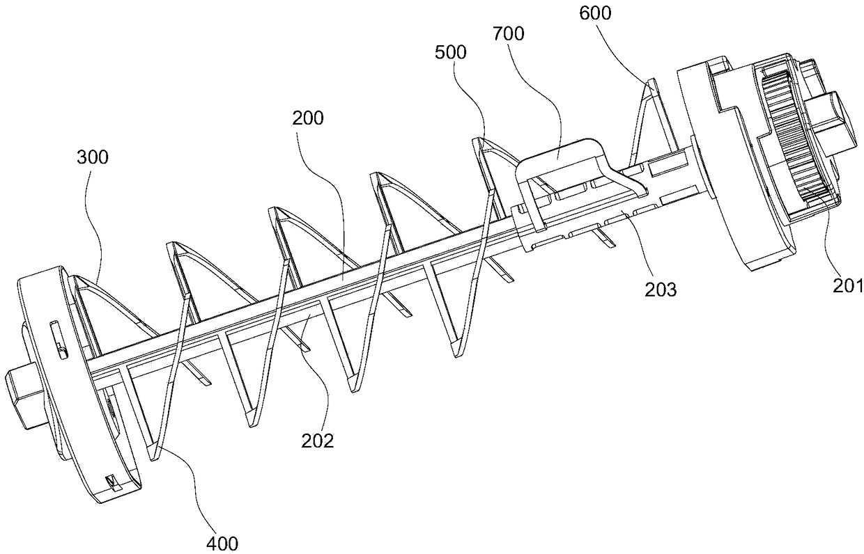
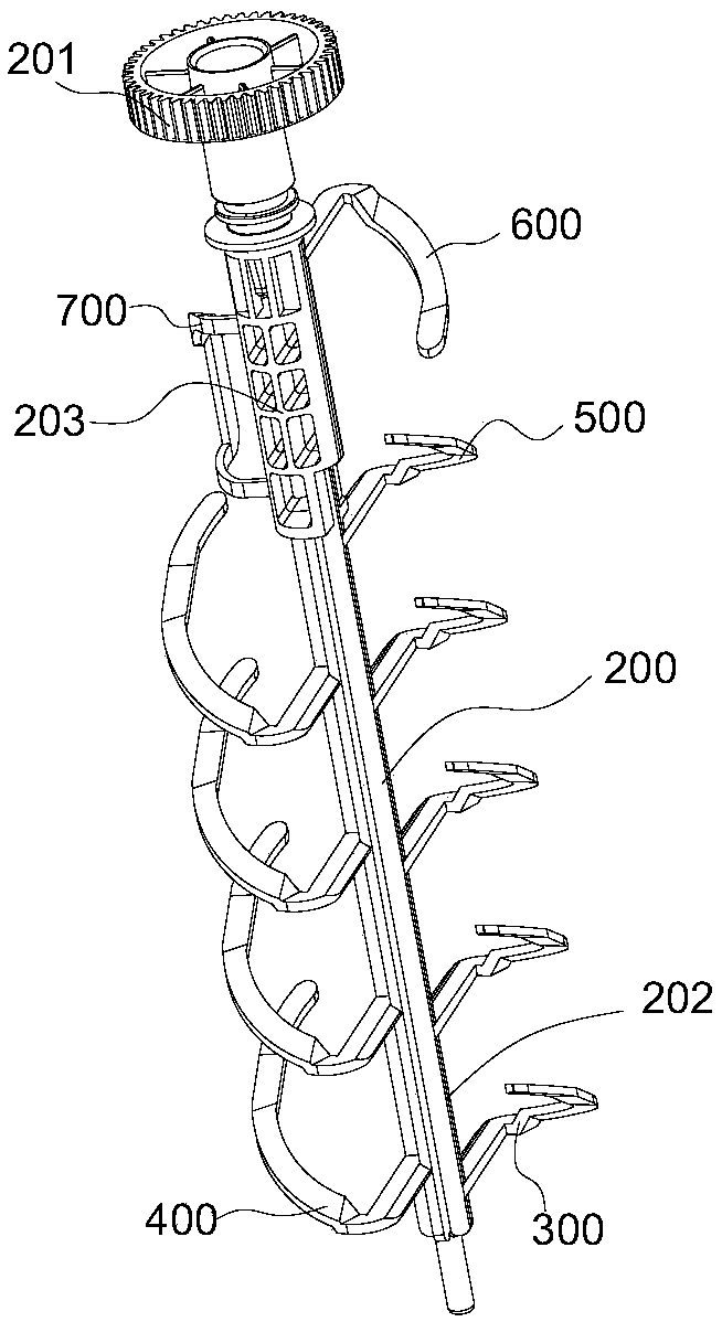
[0023] The invention discloses a container for developer, which includes a cylindrical container body 100 and a rotating shaft 200 located in the container body 100. The two ends of the wall are rotatably connected; one end of the rotating shaft 200 extends out of the container body 100, and this end is provided with a gear 201, and the external dri...


PUM


Abstract

The invention discloses a developer receiving container, comprising a container body, a rotating shaft located in the container body; The container body is provided with a powder outlet. The rotatingshaft is provided with a powder scraping blade for scraping the toner out of the powder outlet, and a plurality of groups of spiral blade groups arranged at equal intervals along the axial direction of the rotating shaft; Each helical blade group includes a first blade, a second blade, and a second blade on opposite sides of the rotating shaft. The first blade is positioned on a side of the secondblade adjacent to the powder outlet; The first blade and the second blade both comprise straight segments, and the ends of the straight segments are connected with spiral segments. The spiral segmentspirally extends along the circumferential direction of the inner cavity of the container; A spiral segment rotation track of any one of the first blades at least partially overlaps with a straight segment rotation track of an adjacent second blade; The rotational trajectory of the helical section of the second blade is located between the rotational trajectory of the straight section of the second blade and the rotational trajectory of the straight section of the adjacent second blade. The rotational trajectory of the helical section of the second blade is located between the rotational trajectory of the straight section of the second blade and the rotational trajectory of the adjacent straight section of the second blade. Compared with the prior art, the invention has the advantages ofsimple structure, fast and uniform material feeding, and less friction and heat generation.

Description

technical field [0001] The invention relates to the field of printing equipment, in particular to a developer container. Background technique [0002] The developer is generally used in electronic imaging equipment, such as printers and copiers, and the developer is generally loaded in a container, such as a toner cartridge. The current toner cartridge has a rotatable stirring shaft inside, and the stirring shaft generally plays the role of transporting toner (ie developer). Most of them have the defect of uneven feeding. In addition, the contact area between the spiral blade and the carbon powder is too large, resulting in excessive frictional heat generation between the carbon powder and the spiral blade. In addition, there is currently another solution for toner transmission: a developer container with a movable push plate, a screw working assembly is formed between the movable push plate and the rotating shaft, and when the rotating shaft rotates, the movable push plate...

Claims


Application Information

Patent Timeline
Patent Type & Authority Applications(China)
IPC IPC(8): G03G15/08
CPCG03G15/0891
Inventor 祝金军何家冰
Owner JIANGXI KAILIDE TECH CO LTD
Why Eureka
Try Eureka