Stripping system

A technology of wire stripping and wire stripping mechanism, which is applied in the direction of dismantling/armoring cable equipment, etc., can solve the problems of reduced feeding rate, poor matching of wire stripping mechanism, and reduced radius of cable coil, etc., to achieve smooth and smooth wire stripping Effect

Active Publication Date: 2019-01-25
格林美(武汉)新能源汽车服务有限公司
View PDF6 Cites 0 Cited by
  • Summary
  • Abstract
  • Description
  • Claims
  • Application Information

AI Technical Summary

Problems solved by technology

[0003] The purpose of the present invention is to overcome the above-mentioned technical deficiencies, and propose a stripping system to solve the technical problems in the prior art that with the consumption of cables, the radius of the cable roll decreases, resulting in a decrease in feeding rate, and poor matching with the stripping mechanism

Method used


Image

  • Stripping system
  • Stripping system
  • Stripping system

Examples


Embodiment Construction

[0021] The technical solutions in the embodiments of the present invention will be clearly and completely described below in conjunction with the drawings in the embodiments of the present invention.

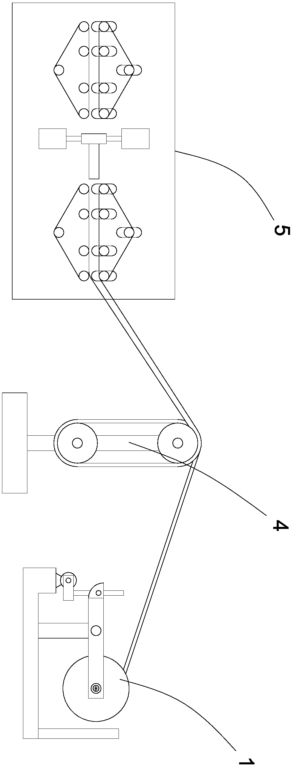
[0022] See figure 1 , figure 1 It is a structural schematic diagram of the wire stripping system provided by the present invention.

[0023] The wire stripping system includes: a wire pay-off mechanism 1 , a transition mechanism 4 and a wire stripping mechanism 5 .

[0024] The transition mechanism 4 is arranged between the pay-off mechanism 1 and the wire-stripping mechanism 5, the cable roll to be processed is placed on the pay-off mechanism 1, the cable protrudes from the pay-off mechanism 1, and is wound on the transition mechanism 4 once Afterwards, enter in the stripping mechanism 5 and carry out stripping, cutting process.

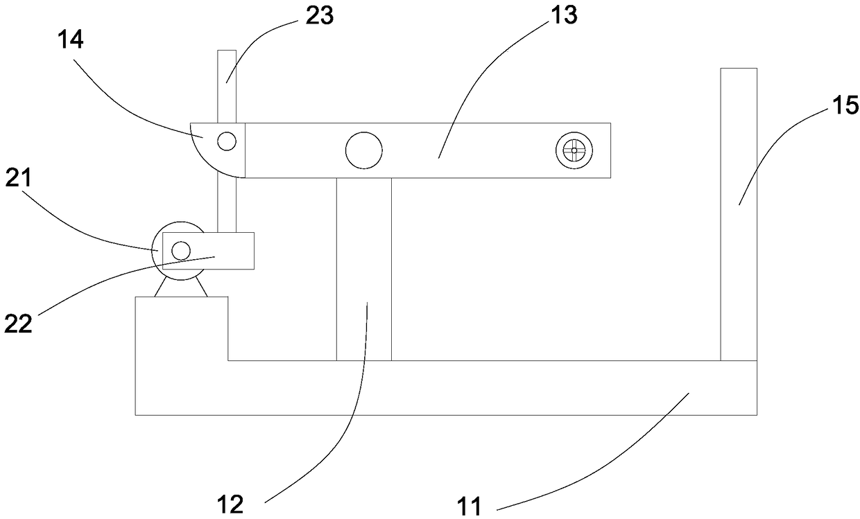
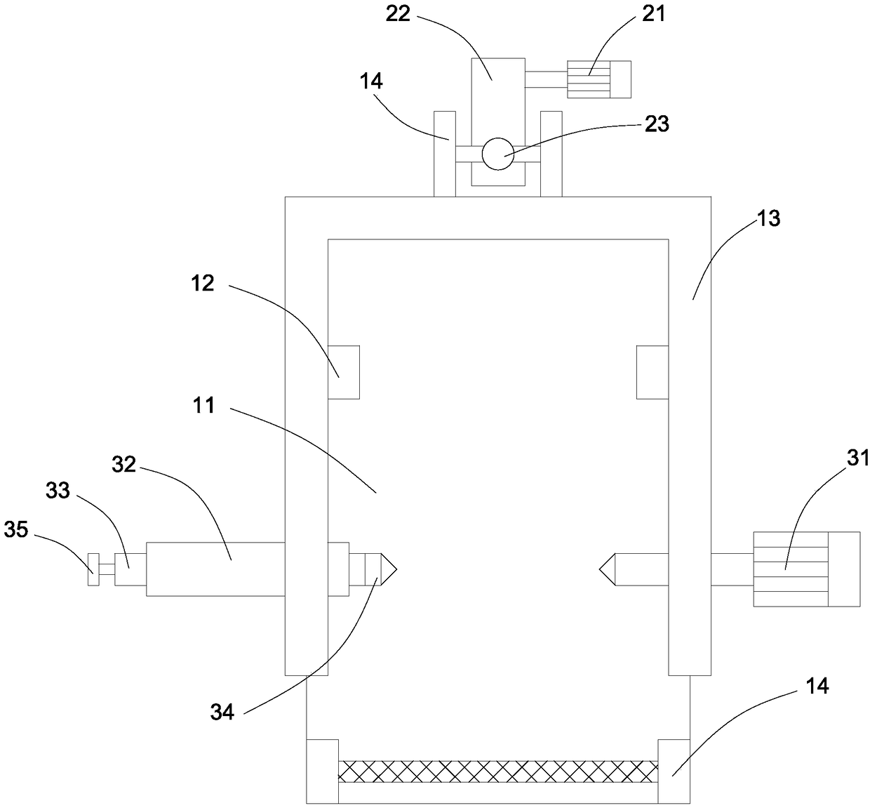
[0025] See Figure 2 to Figure 4 , figure 2 yes figure 1 Side view of the middle pay-off mechanism; image 3 yes figure 1 Top view of the mi...


PUM


Abstract

The embodiment of the invention discloses a wire stripping system, comprising: a wire stripping mechanism, comprising a frame body and a clamping wire stripping assembly, wherein the frame body comprises a U-shaped frame, and the clamping wire stripping assembly comprises a wire stripping motor, a sleeve, a clamping shaft and a rotating head; A thread stripping mechanism comprising a plate frame,two feeding mechanisms and a shearing assembly; The transition mechanism is arranged between the setting-out mechanism and the stripping mechanism, and comprises a transition frame, a certain pulley and a movable pulley, wherein the fixed pulley is rotatably connected with the transition frame, and the fixed pulley and the movable pulley form a pulley set. A thread stripping mechanism includes a transition mechanism, the transition mechanism mainly comprises a pulley block, when the feeding rate is higher than the stripping rate, the excess cables are stored in the pulley block, when the feeding rate is lower than the stripping rate, the cables stored in the pulley block are supplemented, so that the stripping motor only needs to provide an average rate to ensure smooth stripping.

Description

technical field [0001] The invention relates to the technical field of cable processing, in particular to a wire stripping system. Background technique [0002] During the production process, the factory usually winds a cable into a roll for storage. When in use, the cable is cut to the required length, and the plastic sheaths at both ends are removed before use. In the existing production process, it is generally processed by a wire stripping machine. Since the cable is wound into a roll, the radius of the cable roll is large at the beginning. If the pay-off motor rotates and feeds at a constant rate, the feeding rate is the fastest at the beginning. As the cable is used, the radius of the cable roll decreases and the feeding The rate gradually decreases. However, the shear rate of the cable stripping is constant, resulting in an unsmooth fit between the two. Contents of the invention [0003] The purpose of the present invention is to overcome the above-mentioned tech...

Claims


Application Information

Patent Timeline
Patent Type & Authority Applications(China)
IPC IPC(8): H02G1/12
CPCH02G1/12Y02W30/82
Inventor 许开华张宇平宋琦刘忠武
Owner 格林美(武汉)新能源汽车服务有限公司
Why Eureka
Try Eureka