Electric motor

A motor and fan technology, applied in asynchronous induction motors, electric components, electromechanical devices, etc., can solve the problems of easy contact with rainwater and dust, excessive heating of the rotor, and shortened bearing life, etc., to achieve easy combined cooling, high power density, Life-enhancing effect

Inactive Publication Date: 2019-01-25
高建鑫
View PDF0 Cites 2 Cited by
  • Summary
  • Abstract
  • Description
  • Claims
  • Application Information

AI Technical Summary

Problems solved by technology

The filter and dust removal device needs to be disassembled and cleaned regularly, and the cycle is about 3 months, which consumes a lot of labor
[0009] 5. At present, low-floor trams are rapidly popularized in China, and the traction motors of trams are close to the road surface, which is easy to contact with rain and dust, so enclosed traction motors must be used; in order to increase the space for passengers and passages above the bogie, traction motors are required The volume is small enough; in order to meet the performance of greater slope passing performance and improve the braking energy recovery rate, the power of the traction motor is required to be large enough. These factors pose a huge challenge to the current design of traction motors
[0010] 6. The rotor of the three-phase asynchronous motor generates a lot of heat. Usually, the operating temperature of the rotor is 50 to 100 degrees higher than that of the stator. The heat of the rotor is easily transmitted to the bearing through the shaft. The high operating temperature of the bearing will reduce the performance of the grease and reduce the life of the bearing.
The excessive expansion of the inner ring of the bearing may cause the working clearance of the bearing to disappear, the bearing will be stuck and the motor will be burned

Method used


Image

  • Electric motor
  • Electric motor
  • Electric motor

Examples


Embodiment Construction

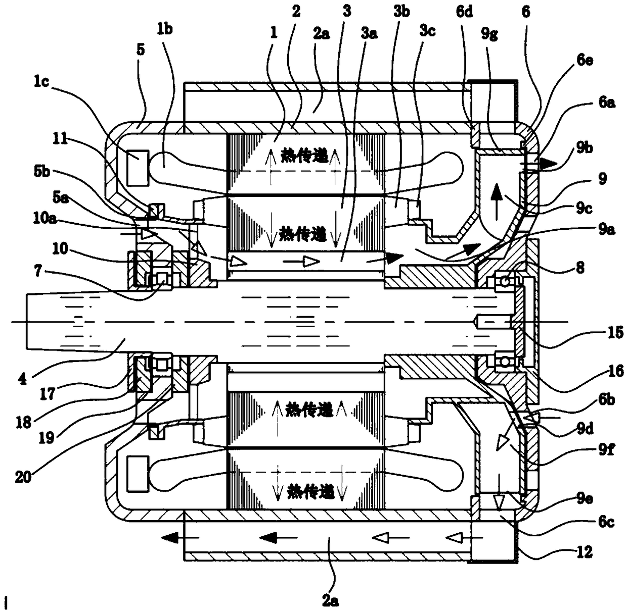
[0085] Referring now to the drawings, wherein like reference numerals indicate like or corresponding parts throughout the several views, in particular the accompanying figure 1 The first embodiment of the present invention has been described.

[0086] figure 1 It is the axial sectional view of the first embodiment of the present invention, refer to below figure 1 Describe the implementation mode:

[0087] Process 1. The stator 1 includes a stator core and a stator coil. There are many slots evenly distributed on the inner circumference of the stator core, and the stator coil is fixed in these slots. Each stator coil is a series connection of multi-turn windings, so the end winding 1b is essential and is arranged at both ends of the stator core. The stator coils need to be grouped and connected regularly, so there are many joints 1c, figure 1 The middle winding connection 1c is arranged at the left drive end. The stator core is fixed on the inner circumference of the shell...


PUM


Abstract

The invention discloses a fully enclosed motor which adopts a dual-channel fan to realize stator-rotor separate cooling, and adopts a unique dual-channel fan 9 with a motor structure to realize a combined cooling mode of stator enclosed ventilation cooling and rotor open ventilation cooling of a three-phase asynchronous motor. This combined cooling method ensures the reliability of stator insulation and the heat dissipation ability of rotor, and improves the efficiency of the motor. The dual-channel fan 9 is capable of functioning as two fans, so that the motor structure is compact. The bladesof the two-channel fan 9 are divided into two groups 9c and 9f, which are circumferentially staggered. The air ducts 5a, 10a, 3a, 9a, 9c, 9b, 6a form independent rotor cooling ducts; The air ducts 6b, 9d, 9f, 9e, 2a form separate stator cooling ducts. The protrusion 5b forms a labyrinth seal with the toothed disk 11; Fan out circle 9g cooperates with small clearance of convex 6d and 6e to isolatethat stator and rotor spaces.

Description

technical field [0001] The invention relates to a fully enclosed self-ventilated motor for industrial application. Background technique [0002] The heat generated by the stator and the rotor of the three-phase asynchronous motor accounts for about half. The heat generated by the stator of the industrial motor is slightly higher. Due to the large workload and the large slip of the rotor of the traction motor, the heat generated by the rotor will reach more than half of the total heat generated. [0003] The ventilation and cooling methods of three-phase asynchronous motors are usually divided into open type and closed type. [0004] 1. For the existing open motor: the external cooling air flows directly through the surface of the stator and rotor, taking away most of the heat, and the cooling effect is good. The disadvantage is that the stator coil insulation system is easily eroded by external dust, moisture, and oil. According to the statistics of the International Elect...

Claims


Application Information

Patent Timeline
Patent Type & Authority Applications(China)
IPC IPC(8): H02K9/06H02K9/08H02K1/32H02K1/20H02K5/10H02K17/16
CPCH02K1/20H02K1/32H02K5/10H02K5/20H02K9/06H02K9/08H02K17/165
Inventor 不公告发明人
Owner 高建鑫
Why Eureka
Try Eureka