Stabilizer device

A stabilizer and cavity placement technology, which is applied in spraying devices, spray booths, etc., can solve the problems of inconvenient operation, large floor space, complex structure, etc., and achieve the effects of stable device structure, convenient operation, and simple structure

Inactive Publication Date: 2019-01-29
何仙凤
View PDF0 Cites 4 Cited by
  • Summary
  • Abstract
  • Description
  • Claims
  • Application Information

AI Technical Summary

Problems solved by technology

[0002] The current surface protection treatment device of the drilling tool stabilizer is processed by brushing, which leads to the unevenness of the brushing surface, and there is no uniform and efficient spraying method. Secondly, the current spraying device has a complicated structure, which is not only inconvenient to operate but also consumes a lot of energy. Increase the processing cost of the stabilizer, and the current stabilizer surface treatment device occupies a large area and cannot be widely used. Therefore, there is an urgent need for a safe, efficient and automated stabilizer device

Method used


Image

  • Stabilizer device
  • Stabilizer device
  • Stabilizer device

Examples


Embodiment Construction

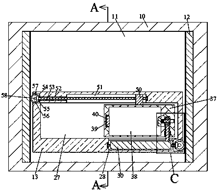
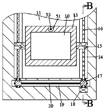
[0012] Combine below Figure 1-4 The present invention is described in detail, and for convenience of description, the orientations mentioned below are now stipulated as follows: figure 1 The up, down, left, right, front and back directions of the projection relationship itself are the same.

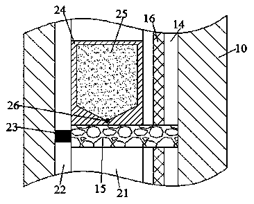
[0013] refer to Figure 1-4 , a stabilizer device according to an embodiment of the present invention, comprising a body 10, the body 10 is provided with a spraying chamber 11, and a left-right symmetrical rack 12 is fixed inside the spraying chamber 11, and inside the spraying chamber 11 A spraying block 13 is provided, and the front and back of the spraying chamber 11 are symmetrically provided with a lifting groove 14 with opposite openings. The lifting groove 14 is provided with a lifting screw 16 whose lower end is fixedly connected with the driving device, and the front and rear end faces of the spraying block 13 are symmetrical. The other end is fixedly provided with the lifting...


PUM


Abstract

The invention discloses a stabilizer device. The stabilizer device comprises a machine body; the machine body is provided with a spraying cavity; bilaterally symmetric racks are fixedly arranged in the spraying cavity; a spraying block is arranged in the spraying cavity; lifting grooves with opposite openings are symmetrically arranged at the front and the rear of the spraying cavity; lifting leadscrews with the lower ends being fixedly connected with a driving device are arranged in the lifting grooves; lifting blocks are symmetrically and fixedly arranged at the front end faces and the rearend faces of the spraying blocks; the other ends of the lifting blocks extend into the lifting grooves and are in threaded connection with the lifting lead screws. The stabilizer device is simple instructure and convenient to operate; the spraying blocks drive a stabilizer to move upwards through a lifting mechanism, while moving blocks move leftward by the transmission of gears and racks in thelifting process, the stabilizer in the stabilizer device rotates, so that the stabilizer carries out comprehensive spraying of protective paint. The stabilizer device is stable in structure, and cancomplete the whole spraying process with only one motor for driving; the stabilizer device is good in linkage, low in energy consumption, high in efficiency, environmentally friendly and suitable foruniversal use.

Description

technical field [0001] The invention relates to the technical field of surface treatment devices, in particular to a stabilizer device. Background technique [0002] The current surface protection treatment device of the drilling tool stabilizer is processed by brushing, which leads to the unevenness of the brushing surface, and there is no uniform and efficient spraying method. Secondly, the current spraying device has a complicated structure, which is not only inconvenient to operate but also consumes a lot of energy. The processing cost of the stabilizer is increased, and the current stabilizer surface treatment device occupies a large area and cannot be widely used. Therefore, a safe, efficient and automatic stabilizer device is urgently needed. Contents of the invention [0003] The object of the present invention is to provide a stabilizer device for overcoming the above-mentioned defects in the prior art. [0004] According to a kind of stabilizer device of the pre...

Claims


Application Information

Patent Timeline
Patent Type & Authority Applications(China)
IPC IPC(8): B05B16/00B05B13/02
CPCB05B16/00B05B13/0235B05B13/0285
Inventor 何仙凤
Owner 何仙凤
Why Eureka
Try Eureka