Annular electrode for electric car charging, charging system and working method

A ring electrode and charging system technology, which is applied in electric vehicle charging technology, electric vehicles, charging stations, etc., can solve the problem of inaccurate docking of docking electrodes, and achieve the effect of precise electrode docking and high power transmission efficiency

Inactive Publication Date: 2019-01-29
JIANGSU WANBANG DEHE NEW ENERGY TECH CO LTD
View PDF7 Cites 0 Cited by
  • Summary
  • Abstract
  • Description
  • Claims
  • Application Information

AI Technical Summary

Problems solved by technology

[0003] Therefore, there is an urgent need to develop a ring electrode for electric vehicle charging, a charging sys

Method used


Image

  • Annular electrode for electric car charging, charging system and working method
  • Annular electrode for electric car charging, charging system and working method
  • Annular electrode for electric car charging, charging system and working method

Examples


Embodiment 1

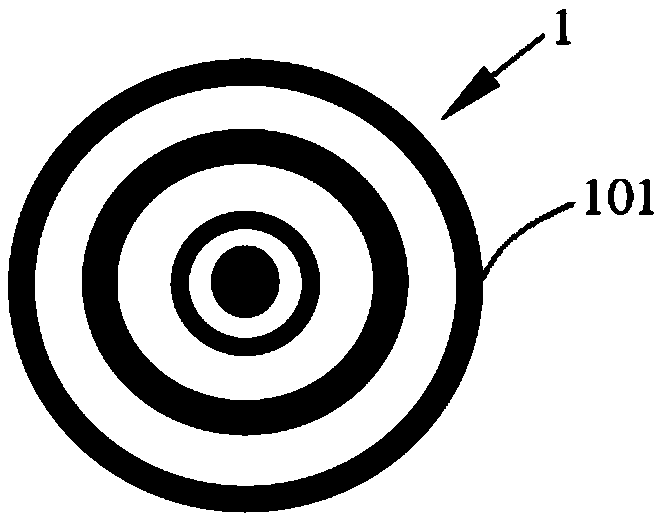
[0025] figure 1 It is a structural diagram of the ring electrode of the present invention.

[0026] In this example, if figure 1 As shown, the present invention provides a ring electrode 1 , which includes: several concentric ring-shaped electrode coils 101 .

[0027] In this embodiment, when charging, the two butt-connected electrodes use a ring-shaped electrode 1 composed of several concentric ring-shaped electrode coils 101, which makes the control of the electrodes more convenient when they are connected, the connection is more accurate, and the power transmission efficiency is higher. high.

Embodiment 2

[0029] figure 2 It is the control schematic diagram of the charging system of the present invention;

[0030] In this example, if figure 2 As shown, this embodiment provides a charging system, including: a processor module, a multi-axis manipulator 2 and a ring electrode 1; wherein the processor module is suitable for controlling the multi-axis manipulator 2 to drive the ring electrode 1 to move to the charging position .

[0031] In this embodiment, the processor module may be, but not limited to, an embedded processor, such as an STM32 processor.

[0032] In this embodiment, the multi-axis robotic arm 2 may be, but not limited to, a three-axis robotic arm, and key motors of each robotic arm are controlled by the processor module.

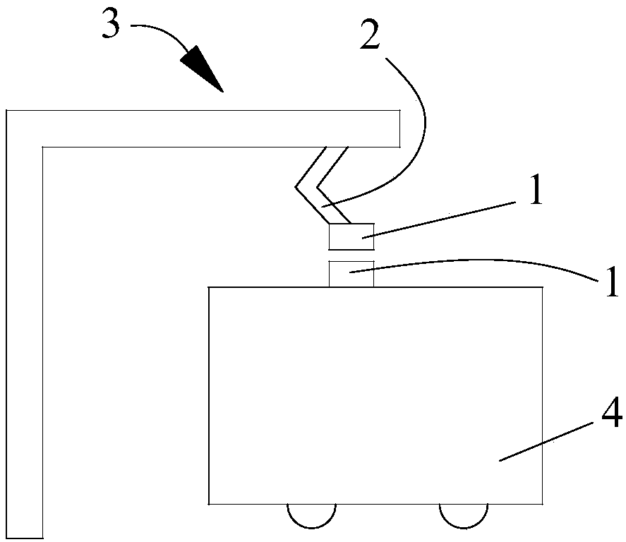
[0033] image 3 It is a structural schematic diagram of the first embodiment of the charging system of the present invention.

[0034] In order to charge electric vehicles 4, such as image 3 As shown, the charging system further includes:...

Embodiment 3

[0043] Such as Figure 4 As shown, in this embodiment, this embodiment provides an electric vehicle 4 equipped with the ring electrode 1 provided in Embodiment 1.

[0044] In order to charge the electric vehicle 4, a multi-axis mechanical arm 2 is arranged on the top of the electric vehicle 4; a processor module is suitable for controlling the multi-axis mechanical arm 2 to drive the ring electrode 1 to the charging position to connect with the charging bow The ring electrode 1 provided on the power supply catenary 5 at the end of 3 is docked to realize power transmission.

[0045] Specifically, the processor module can be used as a control module of the multi-axis robot arm, and the operation process of the multi-axis robot arm can refer to the specific content of Embodiment 2. The processor module may, but is not limited to, use an STM32 processor.

[0046] In this embodiment, the electric vehicle 4 is installed with electrodes as provided in embodiment 1, so that the floo...


PUM


Abstract

The invention relates to an annular electrode for electric car charging, a charging system and a working method. The annular electrode comprises a plurality of circular-ring-shaped electrode coils which are concentrically arranged in a sleeving mode. All butt-joint electrodes adopt the annular electrode constituted by the circular-ring-shaped electrode coils which are concentrically arranged in the sleeving mode, thus the electrodes are in butt joint more accurately, and the electric energy transmitting efficiency is higher.

Description

technical field [0001] The invention relates to the field of electric vehicles, in particular to a ring electrode for charging an electric vehicle, a charging system and a working method. Background technique [0002] At present, the charging bow electrodes of electric vehicles are H-shaped four-electrodes. This shape has a lot of restrictions on the mechanical mechanism of the charging bow that can be automatically aligned. At least half of the mechanical alignment mechanisms cannot maintain the direction of the shaft at the end and will rotate. For example, a four-axis parallel linkage mechanism. [0003] Therefore, there is an urgent need to develop a ring electrode for electric vehicle charging, a charging system and a working method to solve the problem of inaccurate docking between the docking electrodes during charging. Contents of the invention [0004] The purpose of the present invention is to provide a ring electrode for electric vehicle charging, a charging sy...

Claims


Application Information

Patent Timeline
IPC IPC(8): B60L53/16B60L53/35
CPCY02T10/70Y02T10/7072Y02T90/12Y02T90/14
Inventor 朱君亮贡晶晶邵丹薇刘明刚李德胜
Owner JIANGSU WANBANG DEHE NEW ENERGY TECH CO LTD
Why Eureka
Try Eureka