Four-coil receiving device improving mobile wireless electric energy transmission quality, and application of four-coil receiving device

A receiving device and wireless energy technology, which is applied in the direction of circuit devices, power management, transportation and packaging, etc., can solve the problems affecting the use effect of electric vehicles and other equipment, affecting the quality of wireless energy transmission, and damaging energy storage equipment. Effects of transmission efficiency, cost reduction, and pressure reduction on energy storage equipment

Inactive Publication Date: 2017-10-20
SHANGHAI JIAO TONG UNIV
5 Cites 0 Cited by

AI-Extracted Technical Summary

Problems solved by technology

For wireless power transmission on the move, because the position of the power receiving target (equipment that receives or consumes power, such as electric bicycles, electric vehicles, etc.) is moving rapidly, in order to improve the overall magnetic circuit situation in the actual application process Polarity-separated transm...

Method used

As shown in Figure 4, it is mobile wireless charging four coil receiving side parallel mode circuit diagram, two full-bridge rectifier circuits are connected in parallel, so that the receiving e...

Abstract

The invention provides a four-coil receiving device improving mobile wireless electric energy transmission quality, and the device comprises a four-coil receiving structure and an outer rectification circuit. Each two of the coils serve as one group, and the winding directions of the coils of each group are opposite. The coils in the same group are corresponding to different magnetic field polarities at the same moment, and the distance between the two groups of coils is one fourth of the length of the receiving device in space. The two groups of coils are respectively corresponding to the peak and valley of a spatial magnetic field at the angle of the magnetic field. The output end of the two groups of coils are respectively connected with one rectification circuit, and are selectively connected in series or in parallel according to the load conditions. When the two groups of coils are connected in series, the voltages obtained by the two groups of coils through the magnetic field are overlapped, thereby obtaining a higher output voltage. When the two groups of coils are connected in parallel, the loading capability of a wireless transmission secondary side is enabled to be stronger, and more stable power is supplied to a load. The device is widely used in the field of electric car mobile charging, effectively inhibits the fluctuation of the charging voltage of an electric car in a moving process, enables the transmission process of energy to be more stable, and provides a new technical means for the mobile charging of the electric car.

Application Domain

Charging stationsCircuit arrangements +4

Technology Topic

Mobile wirelessCharge voltage +10

Image

  • Four-coil receiving device improving mobile wireless electric energy transmission quality, and application of four-coil receiving device
  • Four-coil receiving device improving mobile wireless electric energy transmission quality, and application of four-coil receiving device
  • Four-coil receiving device improving mobile wireless electric energy transmission quality, and application of four-coil receiving device

Examples

  • Experimental program(3)

Example Embodiment

[0030] Example 1
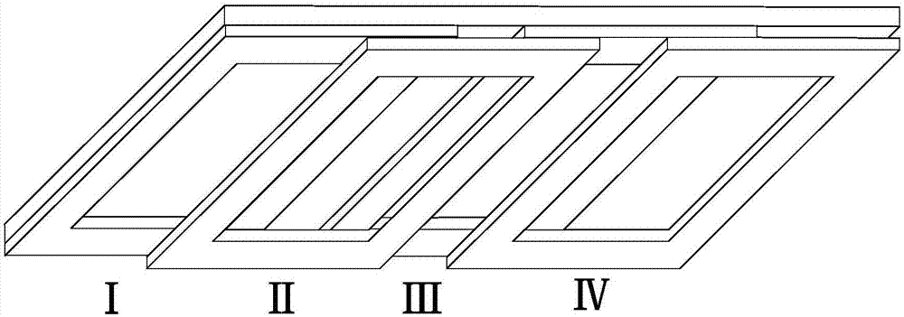
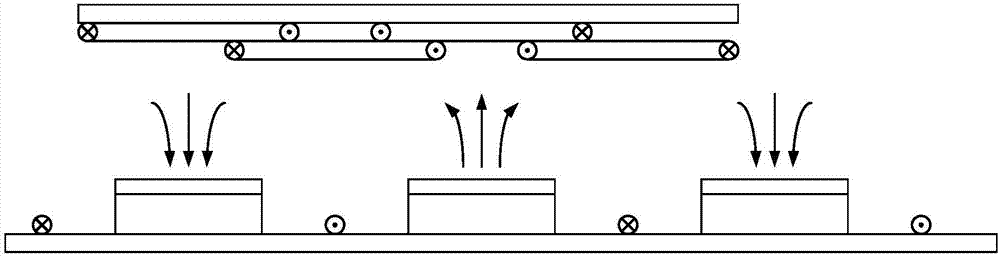
[0031] This embodiment provides a four-coil receiving device for improving the quality of wireless power transmission. It includes two sets of coils. Each set of coils includes two coils. The two coils are connected to each other and face different polarities. Emitter, so that the two coils in each coil group have a phase angle of 180 degrees in the space magnetic field, so that the space magnetic field induces two opposite electromotive forces on the two coils and winds between the two coils. The opposite physical structure allows the electromotive force generated on the two coils to be superimposed.
[0032] The two sets of coil sets have a 90-degree phase angle difference in the spatial magnetic field, so that when one set of coil sets passes the largest magnetic flux, the other set of coil sets passes the smallest magnetic flux.
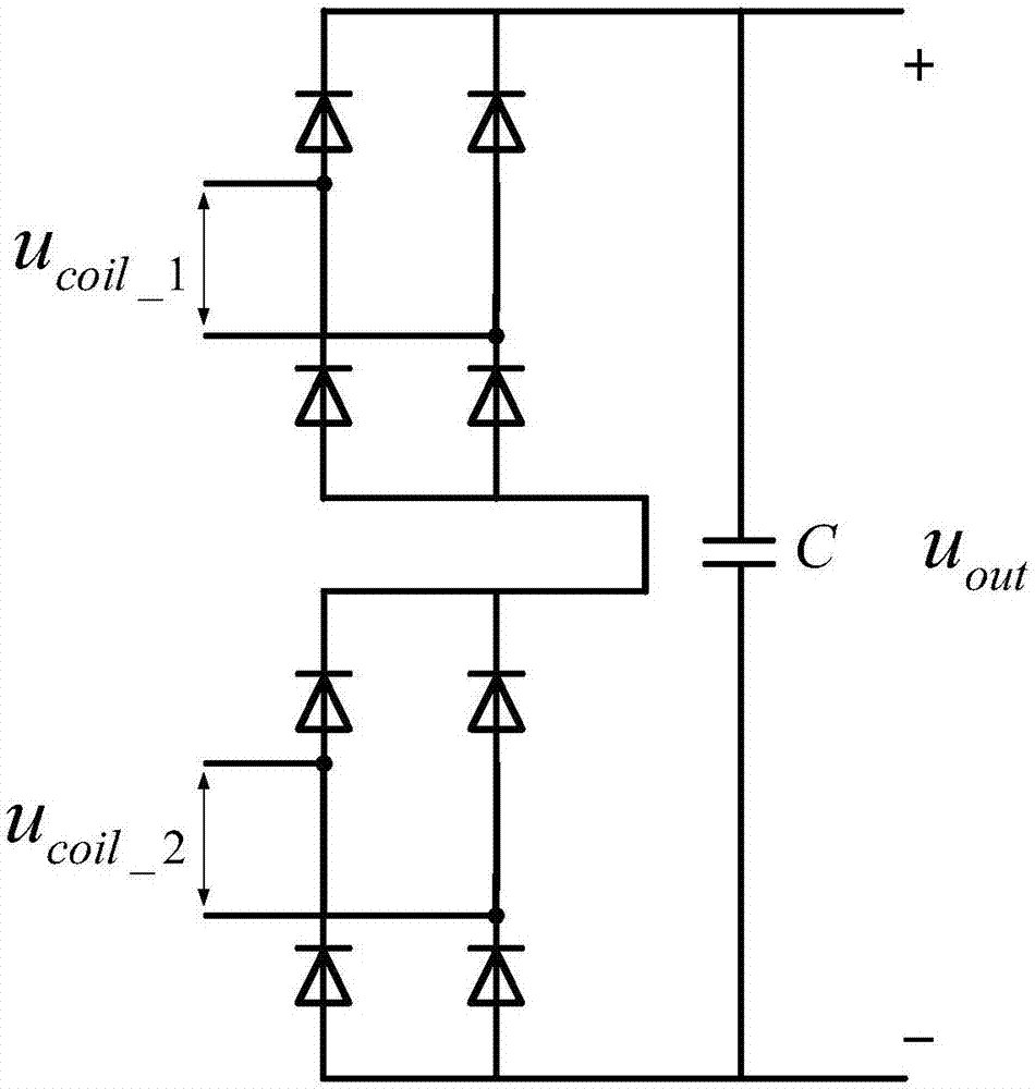
[0033] It also includes an outer rectifier circuit, wherein the output end of each coil group is connected to an outer rectifier circuit.
[0034] The outer rectifier circuit for the above situation includes two connection modes, one is a series superposition mode, and the other is a parallel superposition mode. The series superposition method means that the lead wires of each group of coils are connected to a full-bridge rectifier circuit, and the output terminals of the rectifier circuit corresponding to each group of coils are connected in series to achieve the purpose of voltage superposition. This is for the secondary side load When the output voltage is relatively high; the parallel superposition method refers to connecting the lead wires of each group of coils to a full-bridge rectifier circuit, and paralleling the output terminals of the rectifier circuit corresponding to each group of coils. This circuit mode It is mainly used for load situations that have higher requirements for output voltage stability.
[0035] The four-coil receiving device for improving the quality of wireless power transmission provided by this embodiment has four coils in pairs with opposite winding directions, corresponding to different magnetic field polarities at the same time, and the two coil sets are spatially different from the receiving device length One quarter of the, in the magnetic field angle, correspond to the peak and valley of the space magnetic field respectively. The output ends of the two sets of coils are each connected to a rectifier circuit. According to the needs of the load, two wiring methods are used, series and parallel. When the series wiring is used, the voltages obtained by the two sets of coil sets through the magnetic field will be superimposed on each other, thereby obtaining higher When the parallel connection is used, the wireless transmission secondary side load capacity is stronger, and the load is provided with a more stable power supply; this embodiment can be widely used in the field of electric vehicle mobile charging, effectively inhibiting the charging of electric vehicles during movement Voltage fluctuations make the energy transmission process more stable and provide a new technical means for mobile charging of electric vehicles.

Example Embodiment

[0036] Example 2
[0037] This embodiment provides an application of the four-coil receiving device for improving the quality of wireless power transmission provided by embodiment 1, which is used for mobile wireless charging of electric vehicles (also called "charging while walking"), and decomposes the energy supply track For different polarities, a four-coil receiving device is installed at the bottom of the vehicle. During the movement of the vehicle, the four coils obtain energy at the same time, but the output voltage is relatively stable due to the difference in the phase of the spatial magnetic field.

Example Embodiment

[0038] Example 3
[0039] This embodiment provides an application of the four-coil receiving device for improving the quality of wireless power transmission provided by Embodiment 1. It can be used for all applications that do not have batteries or rely solely on energy storage equipment for insufficient running time or high cost of energy storage equipment. Mobile electrical equipment, when these equipment are in any position of the track laying direction, energy can be directly transmitted from the energy supply track to the receiving equipment end, thereby achieving stable power supply for equipment without energy storage (or less energy storage capacity).
[0040] In this embodiment, the condition that the running time of the energy storage device is insufficient refers to the condition that the running time is less than or equal to 50% of the actual required working time after a full charge.
[0041] In this embodiment, the case where the cost of the energy storage device is too high refers to the case where the energy storage device occupies more than or equal to 20% of the cost of the electrical equipment.
[0042] The above three embodiments are further described below in conjunction with the drawings.
[0043] The difference between Embodiment 1 and the secondary side receiving structure of the traditional mobile wireless charging device is that the traditional secondary side receiving structure of the mobile wireless charging device is a single-coil unipolar structure, while Embodiment 1 adopts a four-coil secondary side receiving structure.
[0044] Such as figure 1 As shown, it is a schematic diagram of a four-coil receiving structure for mobile wireless charging, which includes two sets of coils. Each set of coils includes two coils. The two coils are connected to each other but spaced apart from each other.
[0045] Such as figure 2 As shown, to adopt the mobile wireless charging four-coil receiving structure and the transmitting structure provided in Embodiment 1, the two coils of each coil group are facing the transmitters of different polarities, so that each coil group The two coils in the space magnetic field have a phase angle of 180 degrees, so that the space magnetic field induces two opposite electromotive forces on the two coils and through the physical structure of the opposite winding between the two coils, making the two coils The generated electromotive force is superimposed. The relationship between the two coil sets is as figure 2 As shown, when one of the coil sets is facing a certain pair of magnetic poles, the other set of coils is facing the central axis of a pair of magnetic poles. This makes the magnetic flux passing through the two coil groups present a 90-degree phase difference relationship, that is, when the equivalent total magnetic flux passing through one coil group is the largest, the equivalent total magnetic flux passing through the other coil group is the smallest. This keeps the total magnetic flux through the four coils at a relatively stable level during travel.
[0046] Such as image 3 As shown, it is a circuit diagram of a mobile wireless charging four-coil receiving side series mode circuit diagram. Two full-bridge rectifier circuits are connected in series, so that the voltages induced in the two sets of coils are superimposed on each other, so that the output voltage can be higher.
[0047] Such as Figure 4 Shown is the circuit diagram of the mobile wireless charging four-coil receiving side parallel mode circuit diagram. Two full-bridge rectifier circuits are connected in parallel, so that the receiving end can always work in two sets of coils with better performance, which makes the secondary side's load capacity better. Stronger, the output is more stable.
[0048] The application scenario suitable for the circuit proposed in Embodiment 2 may be a wireless charging road. The wireless charging road is paved with a polarized primary energy transmission structure, such as Figure 5 Shown. A four-coil receiver is suspended under the vehicle, such as Image 6 Shown. When the vehicle is in any place on the charging road, due to the characteristics of the four-coil receiving device and the cooperation of the external series-parallel rectifier circuit, the electric vehicle can reliably provide the energy required for driving.

PUM

no PUM

Description & Claims & Application Information

We can also present the details of the Description, Claims and Application information to help users get a comprehensive understanding of the technical details of the patent, such as background art, summary of invention, brief description of drawings, description of embodiments, and other original content. On the other hand, users can also determine the specific scope of protection of the technology through the list of claims; as well as understand the changes in the life cycle of the technology with the presentation of the patent timeline. Login to view more.

Similar technology patents

Voltage supply module and backlight assembly having the same

InactiveUS20090184667A1improve voltage stability
Owner:SAMSUNG DISPLAY CO LTD

Reactive compensation control method considering fluctuation of offshore wind power

ActiveCN109599897Afully take into accountImprove voltage stability
Owner:NINGBO ELECTRIC POWER DESIGN INST +1

Direct-drive wind power system for wind power plant

InactiveCN103280832AImprove voltage stabilitysimple steps
Owner:LANZHOU JIAOTONG UNIV

Lithium metal battery

ActiveUS20160344063A1improve voltage stability
Owner:SAMSUNG ELECTRONICS CO LTD

Charge and discharge test system based on predictive load feedforward control and control method

PendingCN113098117AImprove voltage stabilityImprove the ability to resist load disturbance
Owner:千黎(苏州)电源科技有限公司

Classification and recommendation of technical efficacy words

  • Improve voltage stability
  • Improve power transmission efficiency

Lithium metal battery

ActiveUS20160344063A1improve voltage stability
Owner:SAMSUNG ELECTRONICS CO LTD

Direct-drive wind power system for wind power plant

InactiveCN103280832AImprove voltage stabilitysimple steps
Owner:LANZHOU JIAOTONG UNIV

Reactive compensation control method considering fluctuation of offshore wind power

ActiveCN109599897Afully take into accountImprove voltage stability
Owner:NINGBO ELECTRIC POWER DESIGN INST +1

Voltage supply module and backlight assembly having the same

InactiveUS20090184667A1improve voltage stability
Owner:SAMSUNG DISPLAY CO LTD

Charge and discharge test system based on predictive load feedforward control and control method

PendingCN113098117AImprove voltage stabilityImprove the ability to resist load disturbance
Owner:千黎(苏州)电源科技有限公司

Induction coil for wireless electric energy transmission, manufacture method, and wireless charging system

ActiveCN104184217AImprove power transmission efficiencyreduce volume
Owner:深圳市安普盛科技有限公司

Grid-connection control method for wind generator sets

ActiveCN108808728AOptimize topologyImprove power transmission efficiency
Owner:TIANJIN UNIV

Layered series-parallel DC power transmission system and DC fault clearing method thereof

ActiveCN111884246AImprove power transmission efficiencyImprove grid flexibility
Owner:HUAZHONG UNIV OF SCI & TECH +2
Why Eureka
Try Eureka