
Device and method for quickly identifying a harmful flow pattern in gathering and transportation vertical pipe

A technology for identifying devices and flow patterns, applied in measuring devices, measuring fluid pressure, fluid dynamics tests, etc., can solve the problems of harsh working environment of underwater sensors, difficult seabed construction technology, and inability to realize rapid identification, etc., and achieve signal The effect of compact collection, improved working environment, and compact device

Pending Publication Date: 2019-01-29
CHINA NAT OFFSHORE OIL CORP +2
View PDF0 Cites 1 Cited by
  • Summary
  • Abstract
  • Description
  • Claims
  • Application Information

AI Technical Summary

Problems solved by technology

However, the system requires underwater measurement; for the built platform, the submarine construction technology required for corresponding transformation is difficult and the construction period is relatively long, which has a greater impact on production; the working environment of the underwater sensor itself is also very difficult. It is even worse, and the low temperature environment on the seabed is prone to blockage of the impulse pipe
The prior art also discloses a flow pattern identification method based on the pressure signal at the top of the gathering riser. This method does not require underwater signals and has a small amount of reconstruction work, and is easy to implement on the built platform; It takes a long time to collect pressure signals, and the required signal length is 5 to 15 times that of the aforementioned rapid identification system (related to the number of identified flow types), which cannot achieve rapid identification

Method used


Image

  • Device and method for quickly identifying a harmful flow pattern in gathering and transportation vertical pipe
  • Device and method for quickly identifying a harmful flow pattern in gathering and transportation vertical pipe
  • Device and method for quickly identifying a harmful flow pattern in gathering and transportation vertical pipe

Examples


Embodiment Construction

[0021] The present invention will be described in detail below in conjunction with the accompanying drawings. However, it should be understood that the accompanying drawings are provided only for better understanding of the present invention, and they should not be construed as limiting the present invention. In the description of the present invention, it should be understood that the terms "first", "second" and so on are only used for the purpose of description, and should not be understood as indicating or implying relative importance.

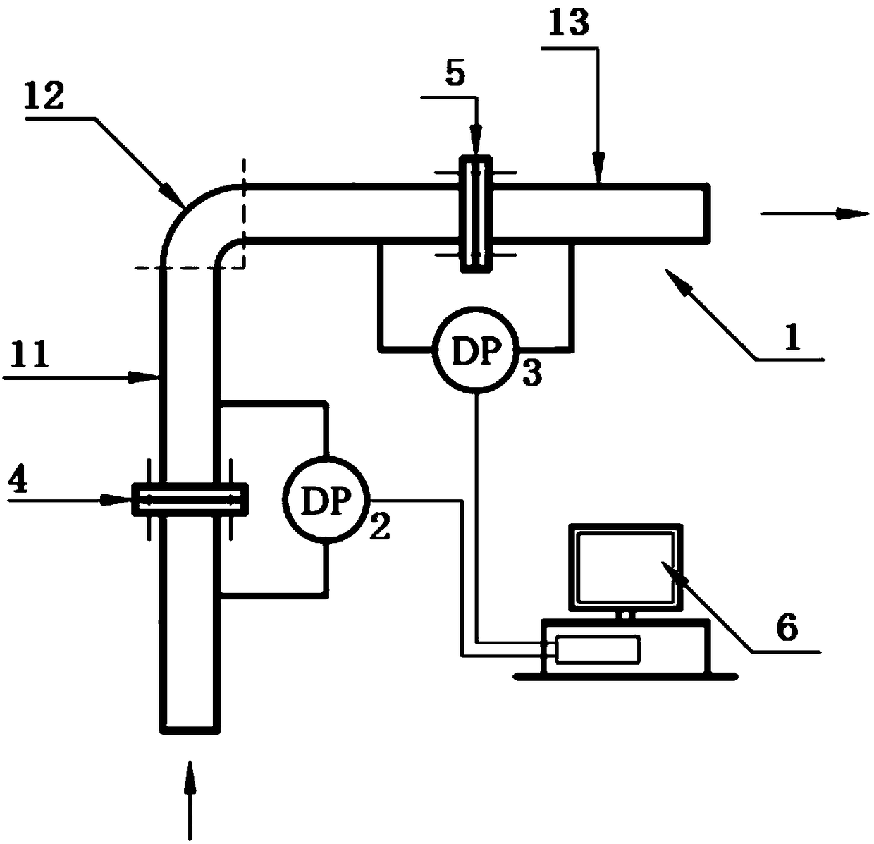
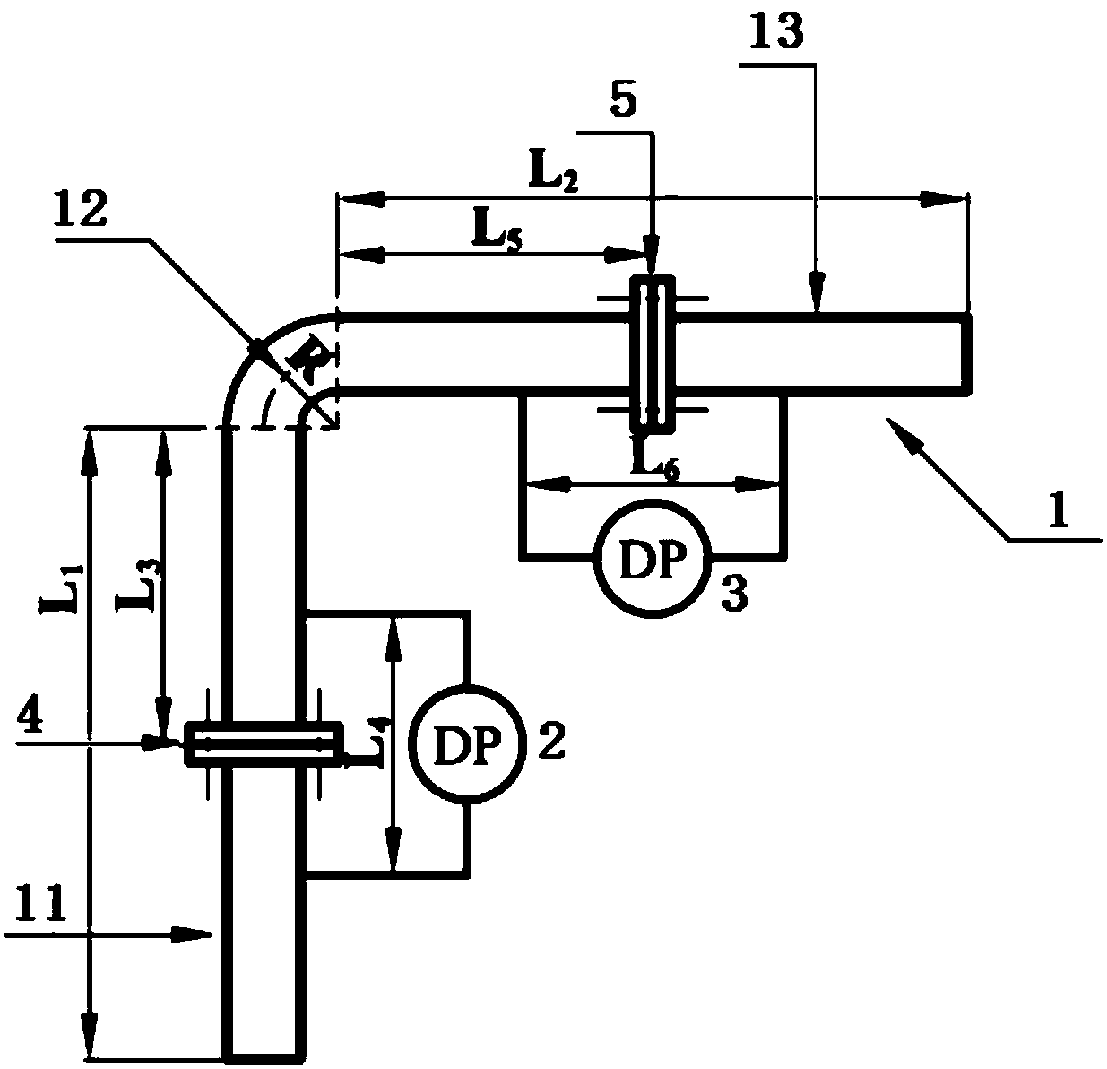
[0022] like figure 1 As shown, the device for quickly identifying harmful flow patterns in the collection riser provided by the present invention includes a vertical-horizontal elbow component 1, a first differential pressure signal sensor 2, a second differential pressure signal sensor 3, a first resistance element 4, a second Two resistance elements 5 and computer 6, wherein, vertical-horizontal elbow part 1 comprises vertical duct 11, 9...


PUM


Abstract

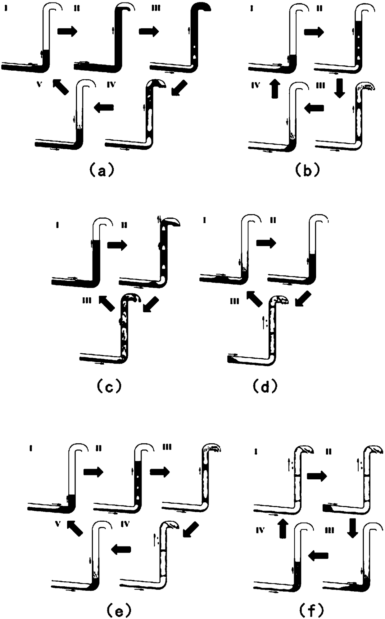
The invention relates to a device and a method for quickly identifying a harmful flow pattern in a gathering and transportation vertical pipe, which comprises the following steps: 1) fixedly connecting one end above a water surface, of a gathering and transportation vertical pipe to one end of a vertical pipe, and connecting the other end of the vertical pipe to one end of a horizontal pipe through an elbow, and fixedly connecting the other end of the horizontal pipe to a gas-liquid separator; 2) arranging resistance components on the vertical pipe and the horizontal pipe; 3) acquiring a differential pressure signal of the pipe at the two resistance components; 4) calculating a mean value and a standard deviation of the differential pressure signal of the pipeline at the two resistance components; 5) calculating the main frequency of the power spectrum of the differential pressure signal of the pipe at the two resistance components; 6) identifying whether the gathering and transportation vertical pipe is a harmful flow pattern, and proceeding to a step 7) when the gathering and transportation vertical pipe is the harmful flow pattern; and outputting the flow pattern identificationresult of the gathering and transportation vertical pipe when the gathering and transportation vertical pipe is not the harmful flow pattern; 7) and identifying the type of the harmful flow pattern ofthe gathering and transportation vertical pipe. The device and method can be widely applied to multiphase flow detection in the petroleum engineering field.

Description

technical field [0001] The invention relates to a device and method for quickly identifying harmful flow patterns in a gathering riser, and belongs to the field of multiphase flow detection in petroleum engineering. Background technique [0002] In the development of offshore oil and gas, because the subsea gas-liquid separation method is not mature enough, the oil and gas produced on the seabed are usually lifted to the production platform on the sea surface by means of mixed transportation. The pipe section is called the gathering riser. Since a platform usually collects the output of multiple oil wells, there is a certain length of pipe section laid along the seabed from the bottom of the gathering riser to the wellhead. When the gas-liquid flow rate is low, long liquid plugs are easily formed in the gathering standpipe, which flows out alternately with the gas phase, resulting in severe fluctuations in the outlet flow rate. This type of flow pattern is called severe slu...

Claims


Application Information

Patent Timeline
Patent Type & Authority Applications(China)
IPC IPC(8): G01M10/00G01L13/00
CPCG01L13/00G01M10/00
Inventor 郭烈锦李清平吴全红秦蕊邹遂丰姚添姚海元程兵李焱朱军龙王清
Owner CHINA NAT OFFSHORE OIL CORP
Learn More