A device and method for realizing dielectric barrier discharge in an in-situ cell of an in-situ infrared analysis device
What is AI technical title?
AI technical title is built by Patsnap AI team. It summarizes the technical point description of the patent document.
A technology of dielectric barrier discharge and analysis device, applied in the field of analysis and detection, can solve problems such as obstacles to mechanism research, little research on intermediate substances, and unclear what substances are formed.
Active Publication Date: 2021-04-20
ZHEJIANG GONGSHANG UNIVERSITY
View PDF8 Cites 0 Cited by
Summary
Abstract
Description
Claims
Application Information
AI Technical Summary
This helps you quickly interpret patents by identifying the three key elements:
Problems solved by technology
Method used
Benefits of technology
Problems solved by technology
[0005] However, there are not many studies on the intermediate substances of active chemical species and reactants produced by these discharges. For example, plasma-coupled catalysts remove PM, VOCs and other pollutants. On the active site of the active site, but what kind of substance is formed and what kind of group is not clear, so that the use of plasma to remove carbon particles, VOCs and NO X Mechanistic studies such as
Method used
Image
Click on the blue label to locate the original text in one second.
Reading with bidirectional positioning of images and text.
Examples
Embodiment 1
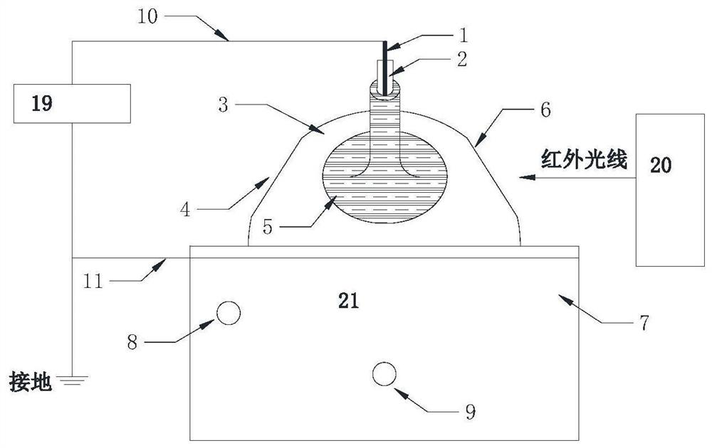
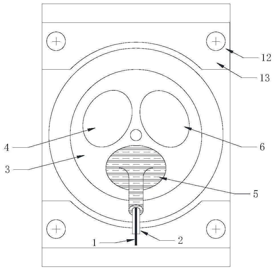
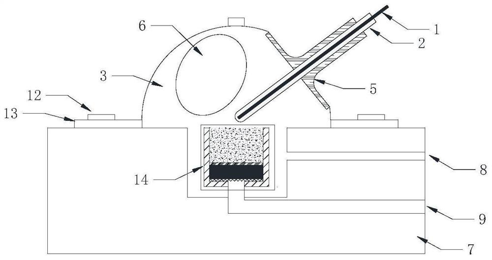
[0058] In this example, the electrode Ⅰ and electrode Ⅱ are made of stainless steel, the insulating tube is made of quartz glass, the electrode Ⅱ is a square plate with no holes, and two high-temperature-resistant circular aluminum oxide gaskets with a thickness of 0.5 mm are placed under the electrode Ⅱ. Thus, the thickness of the sample is 2 mm, and the distance between electrode I and electrode II is 2.5 mm.
[0059] In actual use, the steps are as follows:
[0060] (1) The electrode I1 and the electrode II16 are respectively connected to the high-voltage power supply through the wire I10 and the wire II11, and the wire II11 is grounded at the same time.
[0061] (2) The high-voltage output from the high-voltage power supply is loaded on the electrode I1 and the electrode II16, so that the discharge space above the sample between the electrode I1 and the electrode II16 forms an electric field, and the gas in the discharge space is ionized to generate electrons and ions . ...
Embodiment 2
[0066] Putting Al in the in situ pool 2 o 3 Catalyst, feed CO 2 After adsorption, the catalyst is discharged and regenerated. The purpose is to observe the Al in the discharge plasma field 2 o 3 Changes on the surface of the catalyst, thus inferring that the Al 2 o 3 Reaction mechanism of catalyst regeneration.
[0067] When using it specifically, the steps are as follows:
[0068] (1) Al 2 o 3 The catalyst powder is installed in the sample cell, the surface of the sample is smeared flat, and the gas temperature in the in-situ cell is controlled at 25°C (controlled by a thermostat); the electrode I10 and the electrode II16 are connected to the high-voltage power supply through the metal stainless steel wire I21 and the metal stainless steel wire II22 respectively. Connection, the metal stainless steel wire Ⅱ22 is grounded at the same time.
[0069] (2) In the in-situ cell, the total flow rate of gas is 50mL / min helium for 10min, and the background spectrum is collect...
PUM
Property
Measurement
Unit
thickness
aaaaa
aaaaa
thickness
aaaaa
aaaaa
Abstract
The invention discloses a device and method for realizing dielectric barrier discharge in an in-situ cell of an in-situ infrared analysis device. The device includes: a high-voltage power supply; an infrared spectrometer; an in-situ cell, including a base, a sample pool on the base, and a cover The conical dome above the sample cell is equipped with gas inlet and outlet on the base. The conical dome is equipped with an incident window, an exit window and an observation window. The infrared light enters the sample cell through the incident window, and is reflected and partially After refraction, it emits from the exit window; the dielectric barrier discharge assembly includes an insulating sleeve extending into the conical dome above the sample cell, electrode I inserted into the insulating sleeve, and electrode II set at the bottom of the sample cell, electrode I and electrode II Connect to high voltage power supply. The invention realizes infrared spectrum analysis at the same time as plasma discharge without affecting the analysis result, solves the uncertain factors that may affect the sample in the previous sample transfer process, and makes the discharge process and infrared spectrum analysis process fast and easy.
Description
technical field [0001] The invention relates to the field of analysis and detection, in particular to a device and method for realizing dielectric barrier discharge in an in-situ cell of an in-situ infrared analysis device. Background technique [0002] Plasma is the fourth state of matter besides gas, liquid and solid. As energy levels increase, the state of matter can change from solid to liquid, to gas, and finally to plasma. The forms of low-temperature plasma generated by gas discharge mainly include glow discharge, corona discharge, microwave discharge, and dielectric barrier discharge. The basic process of gas discharge: 1) electrons cause gas breakdown; 2) start to transmit current; 3) electrochemical reaction occurs in the electric field, gas molecules (O 2 、H 2 O, etc.) absorb the energy of electrons to form free radicals (O, OH, etc.); 4) Free radicals with strong oxidation activity cause or participate in a series of chemical reactions in the electric field. ...
Claims
Application Information
Patent Timeline
Application Date:The date an application was filed.
Publication Date:The date a patent or application was officially published.
First Publication Date:The earliest publication date of a patent with the same application number.
Issue Date:Publication date of the patent grant document.
PCT Entry Date:The Entry date of PCT National Phase.
Estimated Expiry Date:The statutory expiry date of a patent right according to the Patent Law, and it is the longest term of protection that the patent right can achieve without the termination of the patent right due to other reasons(Term extension factor has been taken into account ).
Invalid Date:Actual expiry date is based on effective date or publication date of legal transaction data of invalid patent.

