Leaky-wave antenna with step impedance composite left-right-hand structure

A composite left-handed, step-impedance technology, applied in the aerospace field, can solve the problem of radiation gain decline, and achieve the effect of increasing beam width, increasing gain, and improving radiation stopband

Inactive Publication Date: 2019-01-29
NANJING UNIV OF POSTS & TELECOMM
View PDF5 Cites 9 Cited by
  • Summary
  • Abstract
  • Description
  • Claims
  • Application Information

AI Technical Summary

Problems solved by technology

However, when the leaky-wave antenna scans to the side-firing angle, it usually encounters the problem of a large drop in radiation gain, that is, the open stopband problem, which makes it impossible for the leaky-wave antenna to perform continuous scanning from forward to backward.

Method used


Image

  • Leaky-wave antenna with step impedance composite left-right-hand structure
  • Leaky-wave antenna with step impedance composite left-right-hand structure
  • Leaky-wave antenna with step impedance composite left-right-hand structure

Examples


Embodiment Construction

[0018] The objects, advantages and features of the present invention will be illustrated and explained by the following non-limiting description of the preferred embodiments. These embodiments are only typical examples of applying the technical solutions of the present invention, and all technical solutions formed by taking equivalent replacements or equivalent transformations fall within the scope of protection of the present invention.

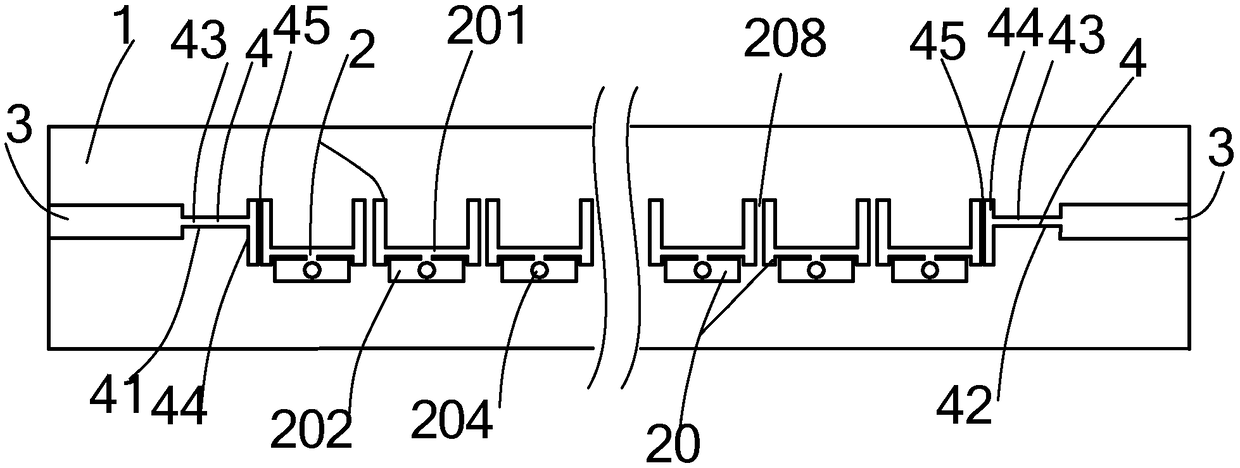
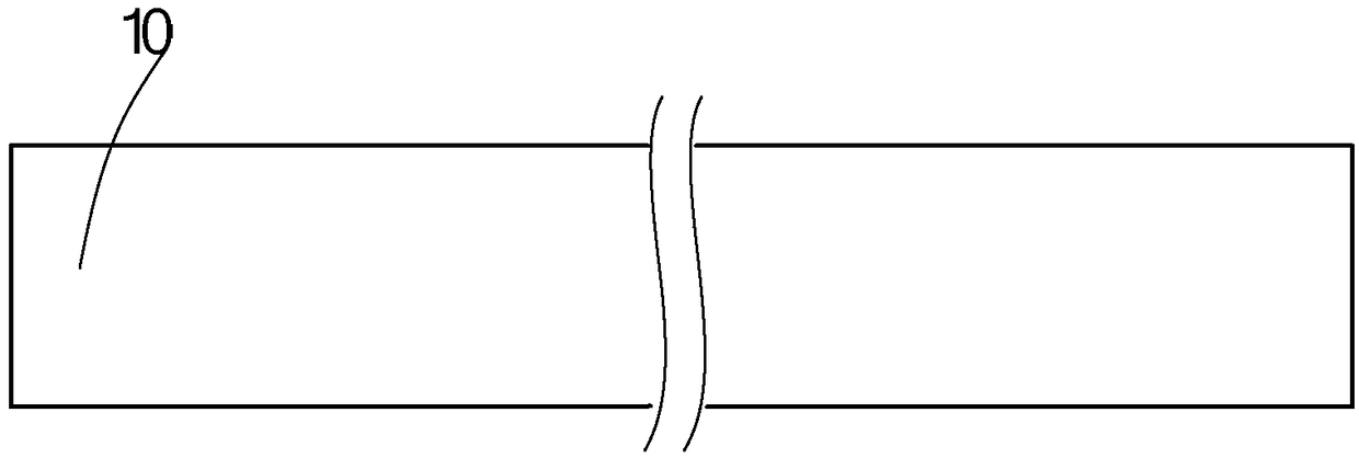
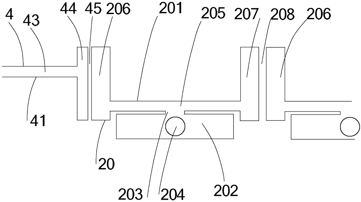
[0019] The invention discloses a leaky wave antenna with a step impedance composite left and right hand structure, such as figure 1 and figure 2 and image 3 As shown, the leaky wave antenna includes a dielectric substrate 1 , a step-impedance radiation array 2 disposed on the dielectric substrate 1 , two microstrip feed lines 3 and two transitions 4 . The backside of the dielectric substrate 1 has a metal layer 10, which is the ground plane of the antenna. Transition 4 connects the microstrip feeder 3 and the step impedance radiation ar...


PUM


Abstract

The invention discloses a leaky-wave antenna with a step impedance composite left-right-hand structure. The leaky-wave antenna comprises a dielectric substrate, a step impedance radiation array arranged on the dielectric substrate, two microstrip feeders and two transitions, wherein the back of the dielectric substrate is provided with a metal layer which is a grounding surface of the antenna; thetransitions connect the microstrip feeders and the step impedance radiation array; the step impedance radiation array is composed of multiple radiation units with the same shape and size; the radiation units are arranged in parallel at equal intervals, the adjacent radiation units are provided with electromagnetic field coupling therebetween but not directly connected through a conductor; and metallized via holes are located at the central positions of rectangular patches and connect from the top surface of the dielectric substrate to the metal layer at the bottom surface. The miniaturizationof the leaky-wave antenna is realized. Meanwhile, the radiation efficiency is improved, the radiation stopband is improved, and continuous scanning from forward to backward is achieved.

Description

technical field [0001] The invention relates to a leaky wave antenna, in particular to a leaky wave antenna with a step impedance compound left and right hand structure, belonging to the field of aerospace. Background technique [0002] Leaky wave antenna is a kind of traveling wave antenna, which can realize frequency scanning characteristics, and has high radiation efficiency and strong directivity. Leaky wave antennas are widely used in aerospace-related fields, such as high-resolution radar, conformal antennas on the surface of aircraft, and navigation antennas, and can also provide better radio coverage for mobile terminals. Among them, the leaky-wave antenna with periodic structure utilizes the spatial harmonics in the high-order mode, which can realize wide-angle scanning, and has become a research hotspot. [0003] Although leaky-wave antennas have many advantages, their large size has always been a disadvantage of leaky-wave antennas. Usually, in order to obtain a...

Claims


Application Information

Patent Timeline
Patent Type & Authority Applications(China)
IPC IPC(8): H01Q1/36H01Q1/48H01Q1/50H01Q13/20H01Q21/06
CPCH01Q1/36H01Q1/48H01Q1/50H01Q13/20H01Q21/065
Inventor 刘蕾蕾陈明宏王元庆
Owner NANJING UNIV OF POSTS & TELECOMM
Why Eureka
Try Eureka