Wiring device for linear motor, linear motor and linear motor system

A technology of linear motors and wiring devices, which is applied in the direction of electromechanical devices, motor generator connectors, parts of connecting devices, etc., can solve problems such as easy damage, cable flexibility decline, internal joint damage, etc., to reduce production cycle time and the effect of reducing manufacturing costs

Active Publication Date: 2019-01-29
GUANGZHOU HAOZHI ELECTROMECHANICAL
View PDF9 Cites 3 Cited by
  • Summary
  • Abstract
  • Description
  • Claims
  • Application Information

AI Technical Summary

Problems solved by technology

[0004] One: After the motor has been running for a long time, when the cable is damaged due to bending fatigue, oil leakage and aging, etc., because the cable cannot be separated from the fuselage, the motor part can only be removed and returned to the factory for repair;
[0005] Second: When the cable is dragged and pulled, because the cable is directly welded to the internal winding, the process of dragging and pulling will have an impact on the internal structure, which may cause damage to the internal joints;
[0006] Third: The cable itself is twisted by multiple sets of core wires, and there are gaps between the wires. The motor potting glue will penetrate into the cable along the gap, causing the cable to be partially hardened, and the hardened cable is flexible. drop, directly affects cable movement, and is prone to damage during repeated twisting and bending movements
[0007] It can be seen that there are unreasonable places in the cable connection of the existing linear motor

Method used


Image

  • Wiring device for linear motor, linear motor and linear motor system
  • Wiring device for linear motor, linear motor and linear motor system
  • Wiring device for linear motor, linear motor and linear motor system

Examples


Embodiment 1

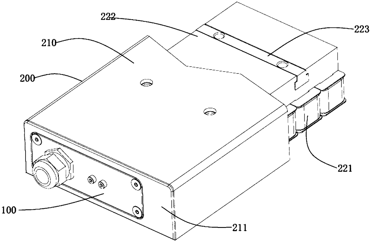
[0051] Such as figure 1 As shown, the embodiment of the present invention provides a linear motor system, including a wiring device 100 and a linear motor 200 .

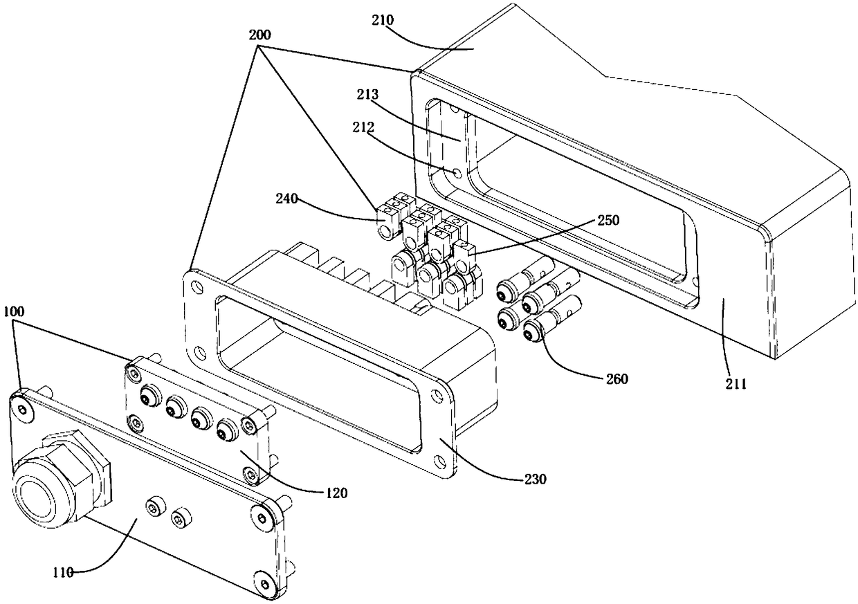
[0052] Such as figure 2 As shown, the wiring device 100 for the linear motor 200 provided by the embodiment of the present invention includes a jumper module 120; Figure 4A , Figure 4B As shown, the jumper module 120 includes an insulating jumper substrate 121, a jumper fixing device 122, a power inlet post 123, a power outlet post 124 and a ground wire post 125, wherein the power inlet post 123 and the power outlet post 124 are Collectively known as the power line terminal. The insulating jumper substrate 121 is provided with a number of terminal mounting holes (not shown), and the power inlet post 123 and the ground wire terminal 125 pass through the terminal mounting holes and are fixedly installed on the insulating jumper substrate 121; 123 and the ground wire terminal 125 are provided with a wiring fixing...

Embodiment 2

[0083] In this example, the star-delta switching of the coil 221 of the linear motor 200 is realized by using the single-layer unit terminal 241 . The internal wiring of the linear motor 200 is as follows Figure 11 The initial state shown in . Among them, A+ is the inlet and outlet of the U-phase winding, A- is the outlet of the U-phase winding... V corresponds to the inlet and outlet of the winding of B, W corresponds to the inlet and outlet of the C winding, and so on. In addition, in this example, U+, V+, and W+ are used for the three phases of the power inlet post 123 to distinguish them; U-, V-, and W- are used for the three phases of the power outlet post 124 to distinguish them; PE mark. In this scheme, no star point is set inside the motor.

[0084] As shown in 12, the star connection scheme: when the user inserts the star connection device 100, the power inlet post 123U+ is only connected to the unit terminal 241 where A+ is located, and the power line outlet post...

Embodiment 3

[0087] As shown in the above-mentioned embodiment 1 and embodiment 2, the specially stacked unit terminals 241 and the power line terminals are connected to each other, and windings of different arrangement sequences can be obtained. The higher the complexity of the stacked unit terminals 241, the more functions realized. more complicated. By superimposing the same stacking scheme, the gears of multiple addition can be obtained. This example is shown in the figure Figure 14 As shown, on the basis of the series-parallel connection jumper scheme of two coils 221 in Embodiment 1, the series-parallel connection scheme of a single set of coils 221 is superimposed, and the series-parallel connection jumper scheme of three coils 221 is obtained. This scheme requires the use of special material of the power line terminal, the power line terminal such as Figure 7 As shown, two conductive rings 1242 are fixed at special positions through injection molding, so that they can connect t...


PUM


Abstract

The invention discloses a wiring device for a linear motor, which comprises an insulation jumper base plate, a jumper fixing device, power incoming line posts, power outgoing line posts and a ground wire binding post, wherein the insulation jumper base plate adopts an injection material, and the power incoming line posts, the power outgoing line posts and the ground wire binding post are injectedand fixedly installed on the insulation jumper base plate; the power incoming line posts and the ground wire binding post are provided with wiring fixing devices at one end of the front of the insulation jumper base plate, the power incoming line post and the ground wire binding post are connected with external cables through the wiring fixing devices; the power outgoing line posts are fixed at the back of the insulation jumper base plate, the power incoming line posts, the power outgoing line posts and the ground wire binding post are mutually insulated, and jumper fixing devices are arrangedon the insulation jumper base plate and used for assembling jumper module on a jumper module installation position on the linear motor. The invention further discloses a linear motor and a linear motor system. The wiring device, the linear motor and the linear motor system disclosed by the invention can realize the separation of a cable and a motor.

Description

technical field [0001] The invention relates to the field of motor equipment, in particular to a wiring device for a linear motor and a linear motor designed using the jumper device. Background technique [0002] The linear motor can be regarded as a rotary motor that is cut radially and unfolded into a straight line. The stator of the rotary motor becomes the primary (also called the mover) of the linear motor, and the rotor of the rotary motor becomes the secondary (also called the stator) of the linear motor. . Rotary motors output torque, and linear motors output thrust. The appearance of the linear motor makes the reciprocating motion no longer need to be realized by the rotation of the complicated screw. At the same time, its high speed, large thrust, and small size have become the first choice for high-speed and high-precision linear feed systems. At present, linear motors are more and more widely used in industrial machinery such as machining centers, electrical di...

Claims


Application Information

Patent Timeline
Patent Type & Authority Applications(China)
IPC IPC(8): H01R13/02H01R13/502H01R27/00H02K5/22H02K41/02
CPCH01R13/02H01R13/502H01R27/00H01R2201/10H02K5/225H02K41/02
Inventor 侯宗毅钟添明汤秀清
Owner GUANGZHOU HAOZHI ELECTROMECHANICAL
Why Eureka
Try Eureka