Wiring device for linear motor, linear motor and linear motor system
A technology of linear motors and wiring devices, applied in electromechanical devices, components of connecting devices, motor generator connectors, etc., can solve problems such as easy damage, cable flexibility decline, internal structure impact, etc., to reduce production cycle , The effect of reducing manufacturing costs
- Summary
- Abstract
- Description
- Claims
- Application Information
AI Technical Summary
Problems solved by technology
Method used
Image
Examples
Embodiment 1
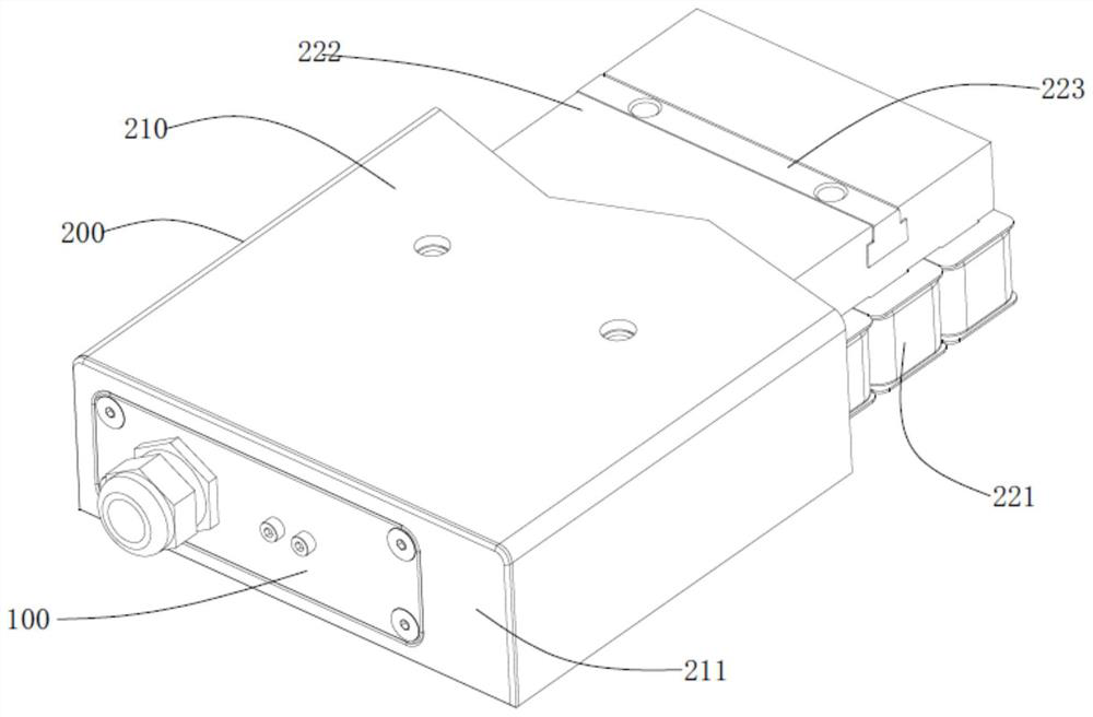
[0049] Embodiment 1: as figure 1 As shown, the embodiment of the present invention provides a linear motor system, including a wiring device 100 and a linear motor 200 .
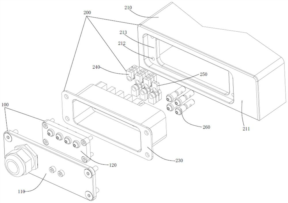
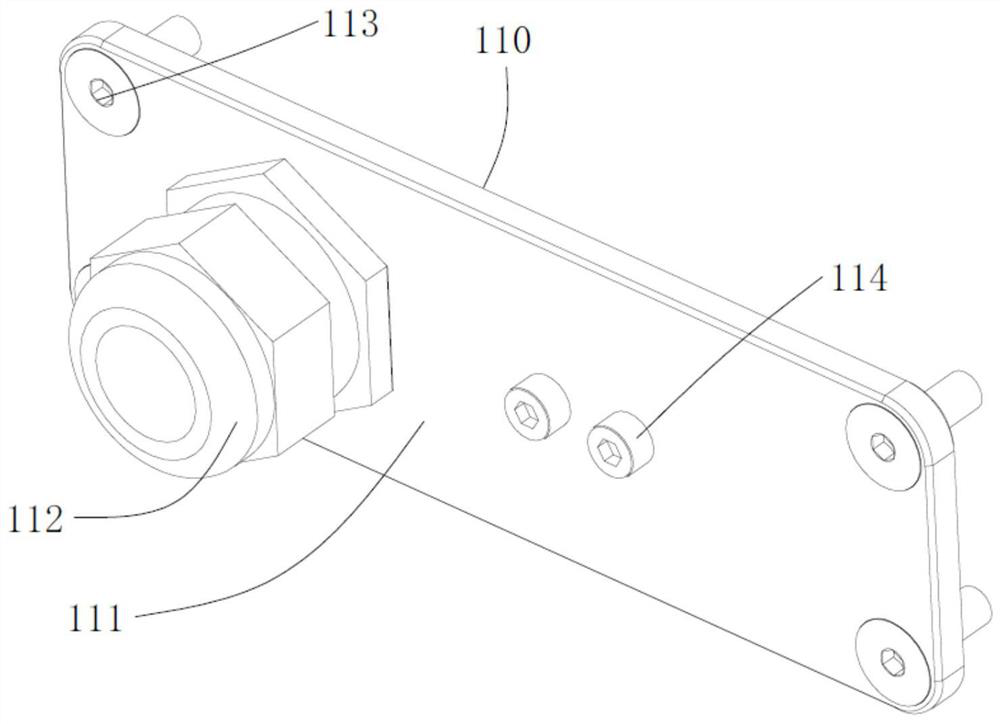
[0050] Such as figure 2 As shown, the wiring device 100 for the linear motor 200 provided by the embodiment of the present invention includes a jumper module 120; Figure 4A , Figure 4B As shown, the jumper module 120 includes an insulating jumper substrate 121, a jumper fixing device 122, a power inlet post 123, a power outlet post 124 and a ground wire post 125, wherein the power inlet post 123 and the power outlet post 124 are Collectively known as the power line terminal. The insulating jumper substrate 121 is provided with a number of terminal mounting holes (not shown), and the power inlet column 123 and the ground terminal 125 pass through the terminal mounting holes and are fixedly installed on the insulating jumper substrate 121; the power inlet column 123 and the ground wire terminal 125 are ...
Embodiment 2
[0077] Embodiment 2: In this embodiment, the star-delta switching of the coil 221 of the linear motor 200 is realized by using the single-layer unit terminal 241 . The internal wiring of the linear motor 200 is as follows Figure 11 The initial state shown in . Among them, A+ is the inlet and outlet of the U-phase winding, A- is the outlet of the U-phase winding... V corresponds to the inlet and outlet of the winding of B, W corresponds to the inlet and outlet of the C winding, and so on. In addition, in this example, U+, V+, and W+ are used for the three phases of the power inlet post 123 to distinguish them; U-, V-, and W- are used for the three phases of the power outlet post 124 to distinguish them; PE mark. In this scheme, no star point is set inside the motor.
[0078] As shown in 12, the star connection scheme: when the user inserts the star connection device 100, the power inlet column 123U+ only connects to the unit terminal 241 where A+ is located, and the power o...
Embodiment 3
[0080] Embodiment 3: As shown in Embodiment 1 and Embodiment 2 above, the specially stacked unit terminals 241 and the power line terminals are connected to each other, and windings with different arrangement sequences can be obtained. The higher the complexity of the stacked unit terminals 241, The functions realized are also more complicated. By superimposing the same stacking scheme, the gears of multiple addition can be obtained. This example is shown in the figure Figure 14 As shown, on the basis of the series-parallel connection jumper scheme of two coils 221 in Embodiment 1, the series-parallel connection scheme of a single set of coils 221 is superimposed, and the series-parallel connection jumper scheme of three coils 221 is obtained. This scheme requires the use of special material of the power line terminal, the power line terminal such as Figure 7 As shown, two conductive rings 1242 are fixed at special positions through injection molding, so that they can conn...
PUM
 Abstract
Description
Claims
Application Information
 - R&D
- Intellectual Property
- Life Sciences
- Materials
- Tech Scout
- Unparalleled Data Quality
- Higher Quality Content
- 60% Fewer Hallucinations
Browse by: Latest US Patents, China's latest patents, Technical Efficacy Thesaurus, Application Domain, Technology Topic, Popular Technical Reports.
© 2025 PatSnap. All rights reserved.Legal|Privacy policy|Modern Slavery Act Transparency Statement|Sitemap|About US| Contact US: help@patsnap.com


