
Shock-proof heat dissipation device for electric tool charger

A technology for power tools and heat sinks, applied in battery circuit devices, circuit devices, current collectors, etc., can solve the problems of damage to the electrical components of the charger, large heat generation, damage to the charger, etc., and achieve easy hot air dissipation and structural design. Reasonable and improve the effect of heat dissipation efficiency

Inactive Publication Date: 2019-01-29
徐州恒永电子科技有限公司
View PDF6 Cites 0 Cited by
  • Summary
  • Abstract
  • Description
  • Claims
  • Application Information

AI Technical Summary

Problems solved by technology

[0002] With the advancement of technology, the current charger has many functions, such as automatic power off when fully charged, and is already a smart charger. However, the charger will still be damaged during use, and it will generate a lot of heat during charging. It needs to dissipate the heat in time to work properly. In addition, car owners usually put the charger in the car and carry it with the car. However, the charger will vibrate up and down with the bumps of the car in the car, which will not only damage the charger shell. It also damages the electrical components used in the charger, making the charger more susceptible to damage

Method used


Image

  • Shock-proof heat dissipation device for electric tool charger
  • Shock-proof heat dissipation device for electric tool charger
  • Shock-proof heat dissipation device for electric tool charger

Examples


Embodiment Construction

[0018] The following will clearly and completely describe the technical solutions in the embodiments of the present invention with reference to the accompanying drawings in the embodiments of the present invention. Obviously, the described embodiments are only some, not all, embodiments of the present invention. Based on the embodiments of the present invention, all other embodiments obtained by persons of ordinary skill in the art without making creative efforts belong to the protection scope of the present invention.

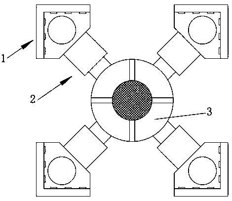
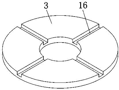
[0019] The present invention provides such as Figure 1-5 The shock-proof heat dissipation device for an electric tool charger includes a lower clamping mechanism 1, a telescopic mechanism 2 and an outer tube 14. The lower clamping mechanism 1 has four groups equiangularly distributed around the outer tube 14, and all of them pass through The telescopic mechanism 2 is connected to the outer tube 14, and can be clamped from the four corners of the charger. At t...


PUM


Abstract

The invention discloses a shock-proof heat dissipation device for an electric tool charger, which comprises lower clamping mechanisms, telescopic mechanisms and an outer tube, wherein four sets of lower clamping mechanisms are distributed at equal angles around the outer tube and are connected with the outer tube through the telescopic mechanisms, each lower clamping mechanism includes a lower clamping piece, a gasket and bumps, clamping ports of the four sets of lower clamping pieces are oppositely arranged, each telescopic mechanism includes a telescopic tube, a clamping spring and a fixed rod, the telescopic tube is a hollow tubular structure with one end being closed, the fixed rod is slidably inserted at the open end of the telescopic tube, the clamping spring is sleeved on the end, which is located inside the telescopic tube, of the fixed rod, the closed end of the telescopic tube is fixedly connected with the lower clamping piece, the end, which is located outside the telescopictube, of the fixed rod is fixedly connected to the upper edge of the cylindrical side surface of the outer tube. The shock-proof heat dissipation device for the electric tool charger has the advantages of reasonable structural design, practicability, reliability and the like, and can be generally popularized and applied.

Description

technical field [0001] The invention belongs to the technical field of electric tool accessories, and in particular relates to a shockproof heat dissipation device for an electric tool charger. Background technique [0002] With the advancement of technology, the current charger has many functions, such as automatic power off when fully charged, and is already a smart charger. However, the charger will still be damaged during use, and it will generate a lot of heat during charging. It needs to dissipate the heat in time to work properly. In addition, car owners usually put the charger in the car and carry it with the car. However, the charger will vibrate up and down with the bumps of the car in the car, which will not only damage the charger shell. It also damages the electrical components used in the charger, making the charger more susceptible to damage. [0003] Therefore for this present situation, there is an urgent need to design and produce a kind of electric tool c...

Claims


Application Information

Patent Timeline
Patent Type & Authority Applications(China)
IPC IPC(8): H02J7/00H05K7/20
CPCH02J7/0042H05K7/20145H05K7/20172
Inventor 李洋郑新功
Owner 徐州恒永电子科技有限公司
Learn More