
Charger module

A charger module and resistor technology, applied in the field of vehicle power transmission and distribution, can solve problems such as high impedance of electromagnetic compatibility, eddy current magnetic field, influence stability and reliability, etc., and achieves that it is not easy to interfere with each other, solves electromagnetic compatibility, and has compact device arrangement. Effect

Pending Publication Date: 2019-01-29
CRRC DALIAN R & D CO LTD
View PDF1 Cites 5 Cited by
  • Summary
  • Abstract
  • Description
  • Claims
  • Application Information

AI Technical Summary

Benefits of technology

This patented innovative design allows for better control over electronic components connected together without increasing their size. It achieves these technical benefits by connecting multiple different parts (such as transistors) within an insulator called a combination busbar, allowing them to connect directly instead of being tied up at one end like traditional connections. Additionally, there're no longer any metal conducting paths around those points where they may get bent during normal operations. Overall, this new technology improves the performance and efficiency of electric chargers while reducing unwanted side effects such as noise induction from nearby metals.

Problems solved by technology

Technological Problem: Current converters use multiple parts such as transformer cabinets, power controllers, insulation systems, etc., making them difficult to install due to their complexity. Additionally, these units require separate connections between different elements like cathode ray tubes, secondary batteries, and ground busbars, increasing the risk of failure modes caused by external factors like vibrations and impact loads.

Method used


Image

  • Charger module
  • Charger module
  • Charger module

Examples


Embodiment 1

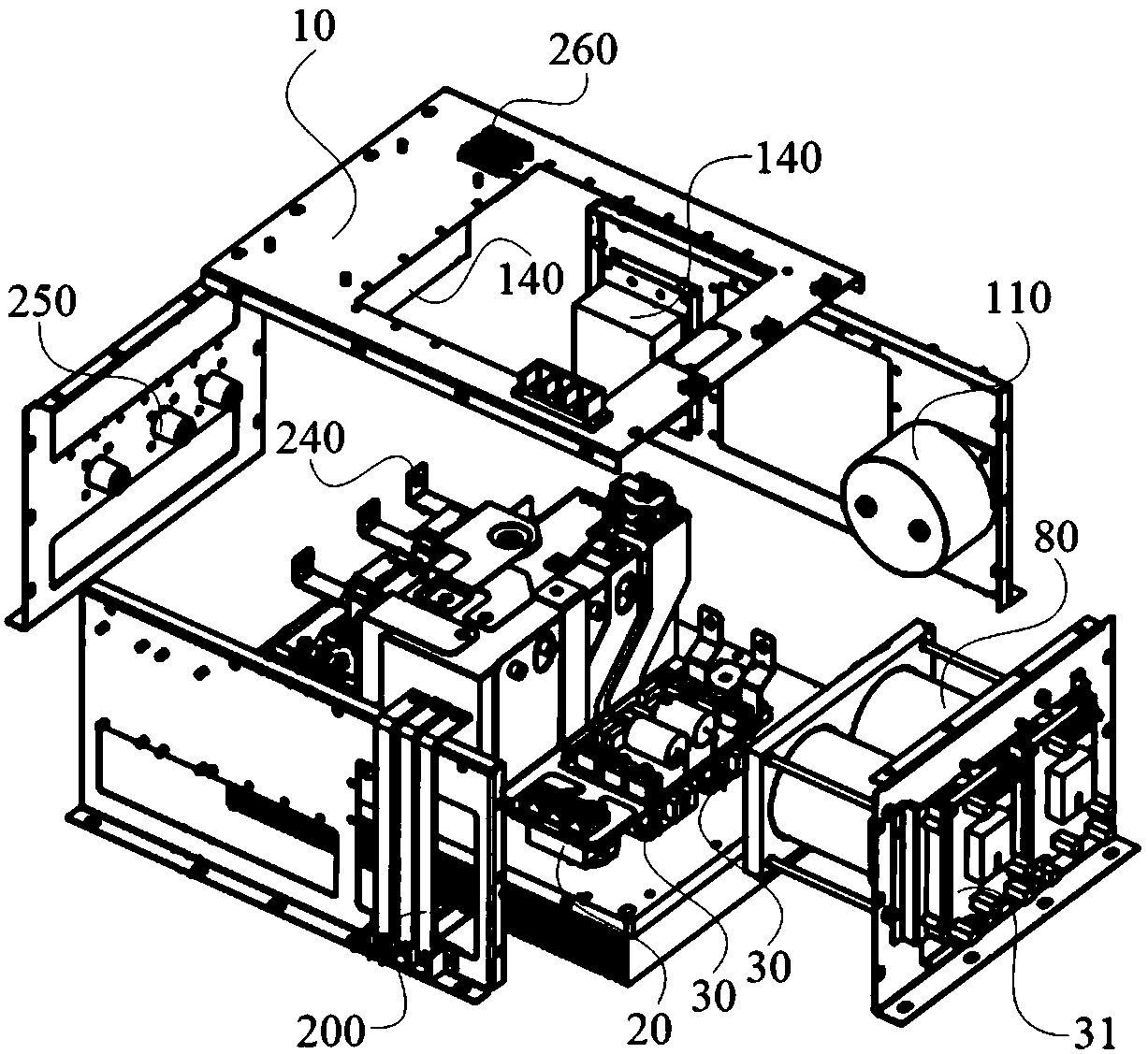
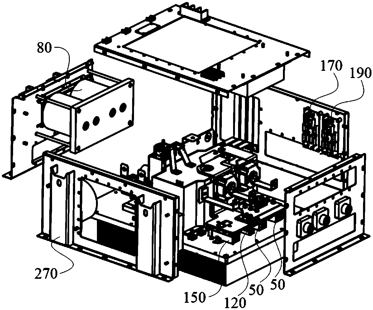
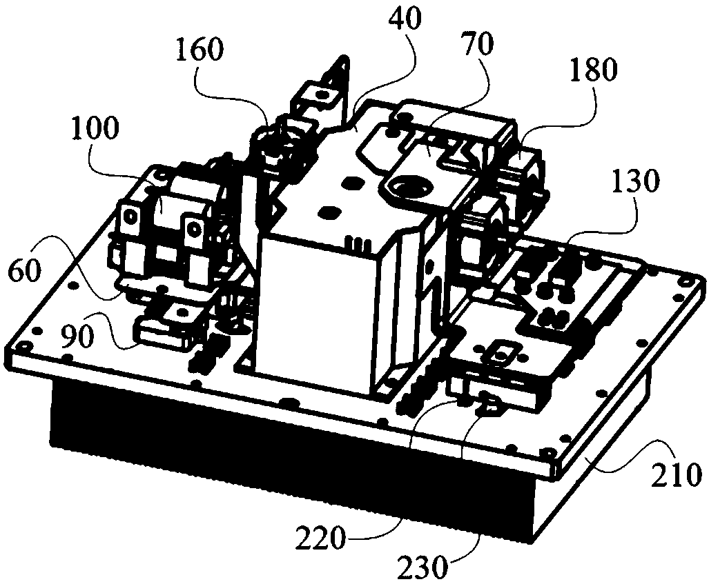
[0041] figure 1 It is a schematic diagram of the split structure of the charger module provided by Embodiment 1 of the present invention, figure 2 It is a schematic diagram of the disassembled structure of the charger module in another direction provided by Embodiment 1 of the present invention, image 3 It is a schematic diagram of the internal structure of the charger module provided by Embodiment 1 of the present invention, Figure 4 It is a schematic structural diagram of the inverter composite busbar and the rectifier composite busbar in the charger module provided by Embodiment 1 of the present invention, Figure 5 It is the electrical principle diagram of the charger module provided by Embodiment 1 of the present invention.

[0042] A charger module provided by an embodiment of the present invention includes a metal frame 10, and the metal frame 10 is provided with an input rectifier unit 20, an IGBT unit 30, a combined transformer unit 40, and an output rectifier un...


PUM


Abstract

The invention provides a charger module, which comprises a metal frame, wherein the metal frame is internally provided with an input rectification unit, an IGBT unit, a combined voltage transformationunit and an output rectification unit, wherein the input rectification unit is used for rectifying flowing three-phase alternating current into direct current, the IGBT unit is used for inverting thedirect current outputted by the input rectification unit into alternating current, the combined voltage transformation unit is used for reducing voltage of the alternating current outputted by the IGBT unit, the IGBT unit is connected with the input rectification unit and the combined voltage transformation unit through an inversion composite busbar, the output rectification unit is used for rectifying the voltage-reduced alternating current into direct current to output, and the output rectification unit is connected with the combined voltage transformation unit through a rectification composite busbar. The charger module realizes the connection of the devices through the rectification composite busbar and the inversion composite busbar, and effectively solves the common electrical problems of electromagnetic compatibility, eddy current magnetic field and high impedance of a high-frequency power supply, so that the charger module is enabled to be more stable and reliable in operationand have excellent compatibility and applicability.

Description


Claims


Application Information

Patent Timeline
Owner CRRC DALIAN R & D CO LTD
Learn More