Thyristor driving circuit and driving method thereof

A technology for driving circuits and driving methods, applied in circuits, electrical components, electronic switches, etc., can solve problems such as power circuit out of control, achieve the effects of reducing electromagnetic radiation, ensuring reliability, and avoiding high-temperature burning

Pending Publication Date: 2019-01-29
嘉兴志嘉智能电器有限公司
View PDF0 Cites 0 Cited by
  • Summary
  • Abstract
  • Description
  • Claims
  • Application Information

AI Technical Summary

Problems solved by technology

Due to the wrong trigger signal sent by the control chip, the suspension/damage of the chip program and other drive signal failures, when the trigger signal SCR2 remains low for a long time, the thyr

Method used


Image

  • Thyristor driving circuit and driving method thereof
  • Thyristor driving circuit and driving method thereof
  • Thyristor driving circuit and driving method thereof

Examples


Embodiment Construction

[0036] The invention discloses a thyristor driving circuit and a driving method of the thyristor driving circuit. The specific implementation manners of the invention will be further described in conjunction with preferred embodiments below.

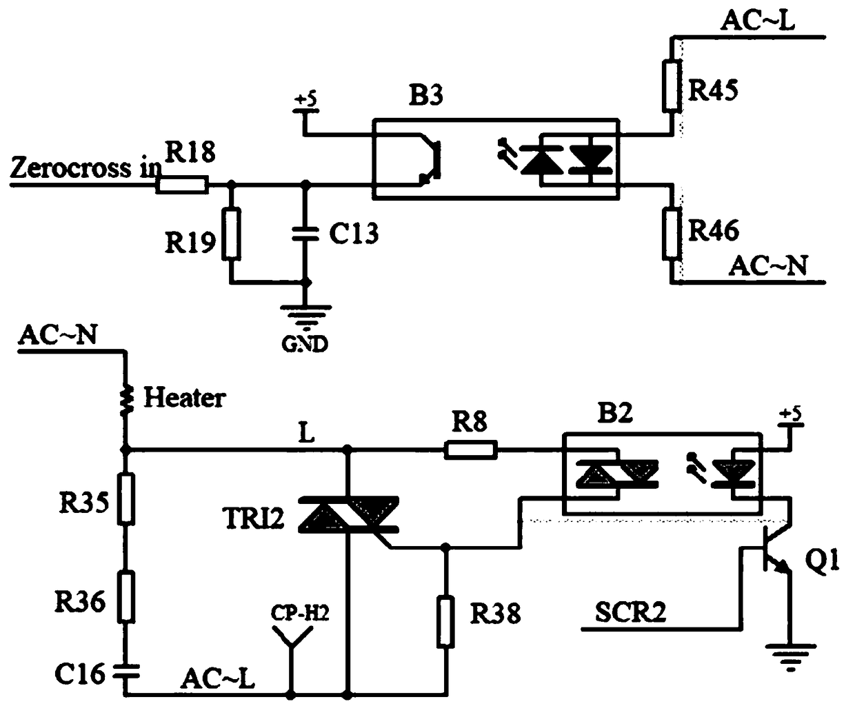
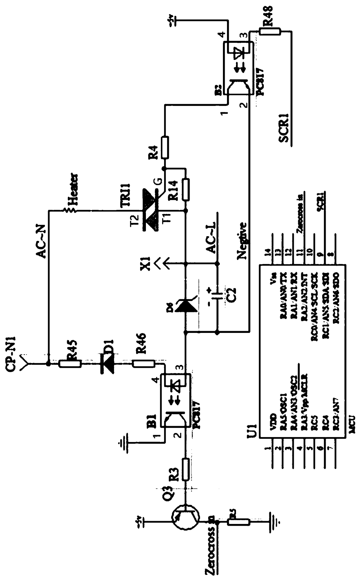
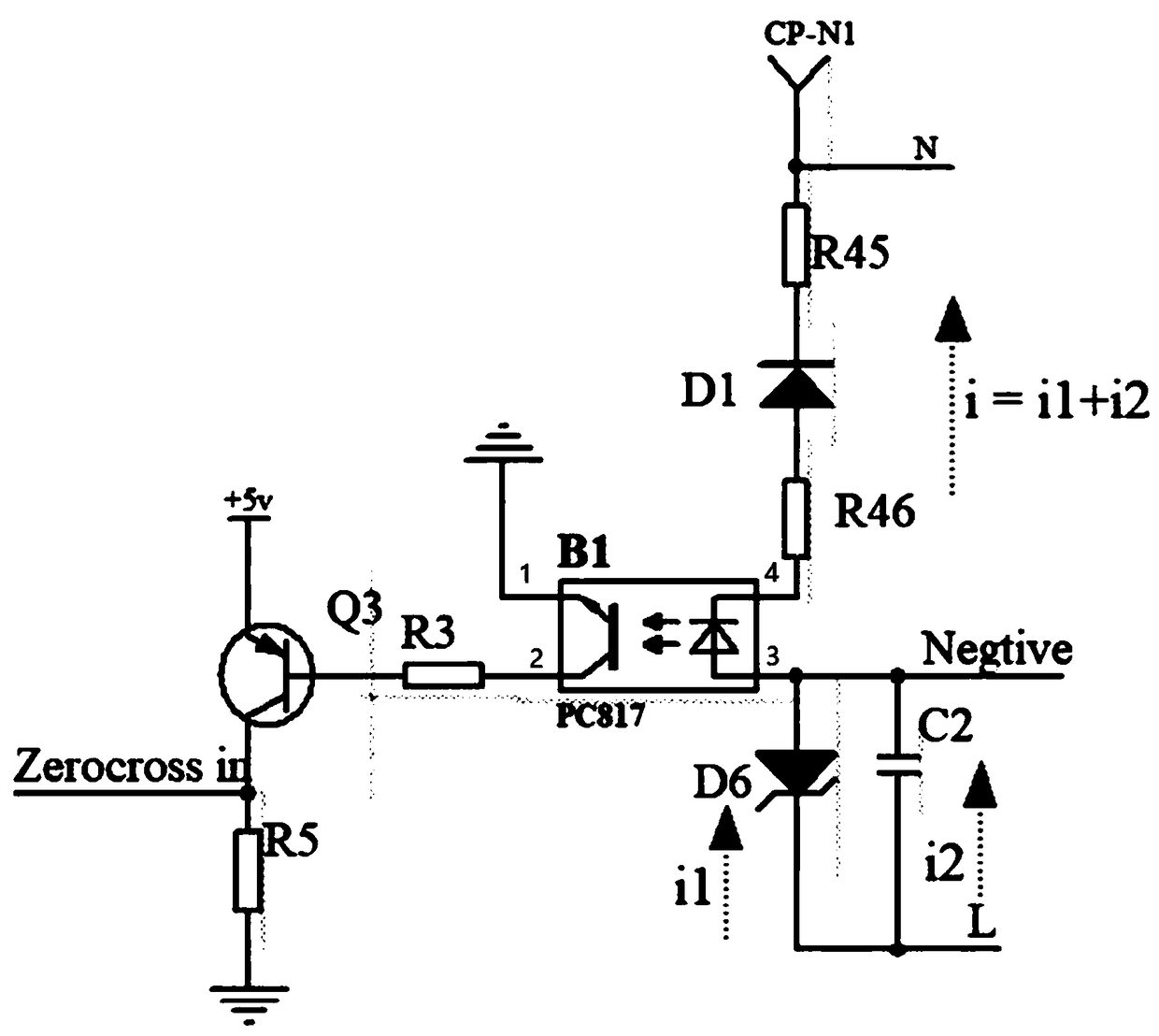
[0037] see attached Figure 2 to Figure 5 , figure 2 and image 3 The circuit structure of the thyristor drive circuit is shown respectively, Figure 4 shows the waveform of the zero-crossing signal, Figure 5 An optimized trigger mode (multi-segment trigger segment) is shown.

[0038] Preferably, the thyristor drive circuit includes an MCU chip U1, a zero-crossing signal circuit, and a thyristor trigger circuit, and the thyristor drive circuit is used to drive the heating element Heater, wherein:

[0039] The strong current side circuit structure of the zero-crossing signal circuit includes a resistor R45, a resistor R46, a rectifier diode D1, and a low-voltage isolation optocoupler B1. One end of the resistor R46 is connected to o...


PUM


Abstract

The invention discloses a thyristor driving circuit and a driving method thereof. The thyristor driving circuit comprises an MCU chip U1, a zero-crossing signal circuit and a thyristor trigger circuit. The thyristor driving circuit is used to drive a heating element Heater. A charge holding circuit is connected between a low-voltage isolation photocoupler B1 and the L wire of the mains supply. According to the thyristor driving circuit and the driving method thereof disclosed in the invention, through ingeniously arranging the charge holding circuit, automatic protection of the thyristor driving under multiple types of fault states can be realized, and potential safety hazards such as high temperature burning are avoided; the thyristor trigger time reference is delayed to be outputted through a timer inside the MCU chip, and zero-crossing signal delay is corrected; and through decomposing the thyristor trigger time to multiple short-time trigger segments, the circuit trigger reliability is ensured, and electromagnetic radiation is reduced at the same time.

Description

technical field [0001] The invention belongs to the technical field of semiconductor power drive, and in particular relates to a thyristor drive circuit and a drive method for the thyristor drive circuit. Background technique [0002] see attached figure 1 , figure 1 A conventional classic thyristor drive control scheme is shown. Specifically, when the zero-crossing signal ZeroCross_in arrives in advance, the MCU immediately sends a low-level trigger signal SCR2 after receiving the signal, drives the zero-crossing optocoupler MOC3041 to turn on, and turns on the peripheral power circuit. [0003] However, the above-mentioned conventional driving scheme has defects, which are briefly described as follows. Due to the wrong trigger signal sent by the control chip, the suspension / damage of the chip program and other drive signal failures, when the trigger signal SCR2 remains low for a long time, the thyristor will always be in the conduction state, resulting in the loss of co...

Claims


Application Information

Patent Timeline
IPC IPC(8): H03K17/081H03K17/79
CPCH03K17/08108H03K17/79H03K2217/0081
Inventor 平志雄翟红雨
Owner 嘉兴志嘉智能电器有限公司
Why Eureka
Try Eureka